All of the tools you need to work with the FPGA Arduino — the Vidor — are now in the wild!
We reported earlier that a series of French blog posts finally showed how all the pieces fit together to program the FPGA on the Arduino MKR4000 Vidor board. Of course, I wasn’t content to just read the Google translation, I had to break out the board and try myself.
I created a very simple starter template, a tool in C to do the bitstream conversion, required, and bundled it all together in one place. Here’s how you can use my starter kit to do your own FPGA designs using the Vidor. I’m going to assume you know about FPGA basics and Verilog. If you don’t, why not check out the FPGA boot camps first?
The first thing you’ll want to do is grab my GitHub repo. You’ll also need the Arduino IDE (a recent copy) and Intel’s Quartus software. Inside, you’ll find three directories, two of which contain slightly modified copies of original Arduino files. But before you start digging in, let’s get the high-level overview of the process.
Basic Concepts
 The FPGA onboard the Vidor is an Intel/Altera device so to configure it, we’ll use Quartus. Usually, Quartus handles everything including programming the device, but we can’t use it for that with the Vidor. Instead, we will have to tell the CPU how we want the FPGA configured and it will do it for us as part of our Arduino program (I really hate saying sketch).
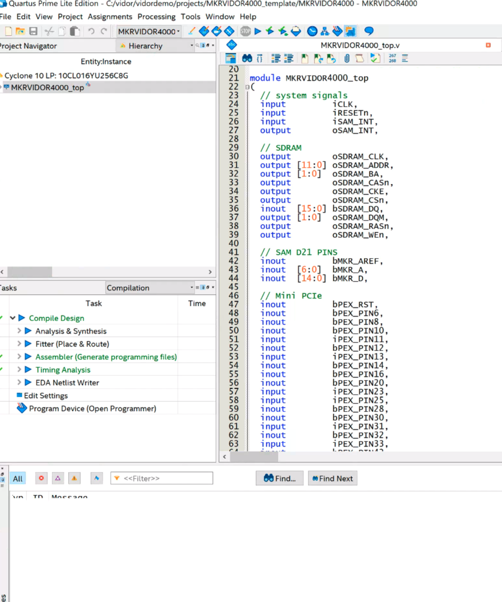
Quartus (see below) will take our Verilog files and create a ttf file that represents the configuration bitstream. This is just an ASCII text file full of decimal numbers. Unfortunately, the way the Vidor is set up, it needs the numbers bit reversed at the byte level. That is, 01 in the ttf file needs to be 80 hex sent to the FPGA.
Arduino supplies a Java class file to do the task, but I got frustrated because the class file needed Java 11 and I didn’t want to put it on every machine I use, so I just rewrote it in C. It is easy enough to port the algorithm, though. In the shell subdirectory, I have another example implementation using awk.
Once you have this stream of numbers, you can include it in an Arduino sketch with some boilerplate to enable the FPGA and load it. The standard program includes the file app.h which is just the output of the conversion program. There’s no C code in it, just comma-separated numbers that the main code will stick in an array at compile-time. Beyond that, it is a normal Arduino program and you can do what you like. Upload it and you’ll get the CPU and FPGA programmed all in one go.
There is one caveat. The FPGA code has a top-level block with lots of I/O pins defined and the corresponding constraints. You should be very careful not to change these or alter the pin constraints. If you drive a pin that’s already an output, for example, you could do real harm to the board. Because all the pins are shared, you have the same problem with the Arduino pins, too. If you are driving an output pin with the FPGA, you shouldn’t try to drive it with the CPU also. However, as you will see, it is perfectly fine to have the FPGA reading a pin from the CPU or vice versa. That’s good because it gives us a way to send data back and forth between them.
On to Code
I wanted something simple, and I didn’t want to accidentally modify the Arduino boilerplate Verilog. You could instantiate a Verilog module, but this would require passing all the I/O pins into the module or modifying the original code every time, both of which I wanted to avoid.
My answer was to use the Verilog `include directive inside the boilerplate. That way your code has access to everything the main module has, but you don’t have to change the main module. The only downside is that Quartus has a smart compile feature that can’t figure out when only an include file changes. So it wasn’t recompiling when I made changes. I turned that feature off in the Quartus options, so if you pick up my example project, you won’t have any problems.
Here’s my example user.v:
reg [27:0] hadcounter;
assign bMKR_D[6]=bMKR_D[5]?hadcounter[27]:hadcounter[21];

always @(posedge wOSC_CLK)
begin
   if (!rRESETCNT[5])
   begin
      hadcounter<=28'hfffffff;
   end
   else
   begin
      if (hadcounter==28'h0) hadcounter<=28'hffffffff; else hadcounter<=hadcounter-28'h1;
   end
end
In the real file, I left a lot of comments in that explains what all the main module has that you can use. But the above is the working part. I define a 28 bit counter. The bMKR_D array is the digital ports for the Arduino and I’m using pin 6 and 5 as an output and an input, respectively.
The assign statement says, in English, If D5 is high, connect the 27th bit of the counter to the LED. If it is low, connect the 21st bit. The rest of the code just makes the counter countdown. I reload the counter even though it would naturally roll over in case you want to fine tune it to a different frequency.
As the counter runs, bit 27 will toggle relatively slowly, but bit 21 will be a good bit faster — that’s just how a counter is. So by changing D5 you can make the LED blink slow or fast.
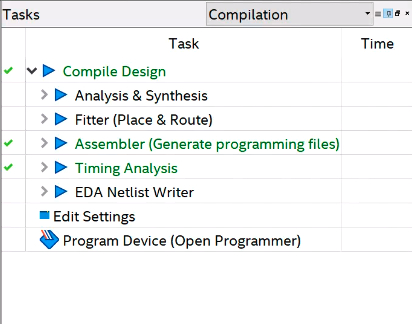 As Verilog goes, this isn’t very complicated or even useful, but it is simple and shows that we can share data with the CPU in both directions. If you open the example project in Quartus, all you really need to do is make any changes to user.v you like, add any other files you want to use and double-click the Compile Design task (see left). If you get a successful compile, you’ll find the ttf file in the output_files directory. That’s the file you need to process with either the Java program, the C program, or the awk script. Either way, collect the output as app.h and put it in the same directory as your Arduino code.
CPU Side
On the sketch side, you need to leave the template code alone since it turns on the FPGA clock, among other things. You’ll notice it also includes app.h and uses a file called jtag.c to communicate with the FPGA. I didn’t segregate the Arduino code into its own include because you probably have to change the setup function, and make changes in global space, but that could be arranged (perhaps make setup call cpu_setup and loop call cpu_loop or something).
If you want to remove the demo parts of the blink-sketch file, you can get rid of:
- The definitions and calls related to FPGAVal, SPEED, and FPGALED
- The Serial calls and definitions
- Everything in the loop function
I left the unmodified code in the EmptySketch directory. Note in the demo code, though that SPEED is an output. This is set to D5, which is an input to the FPGA. By the same token, FPGALED corresponds to D6 and allows the CPU to read the state of the LED output.


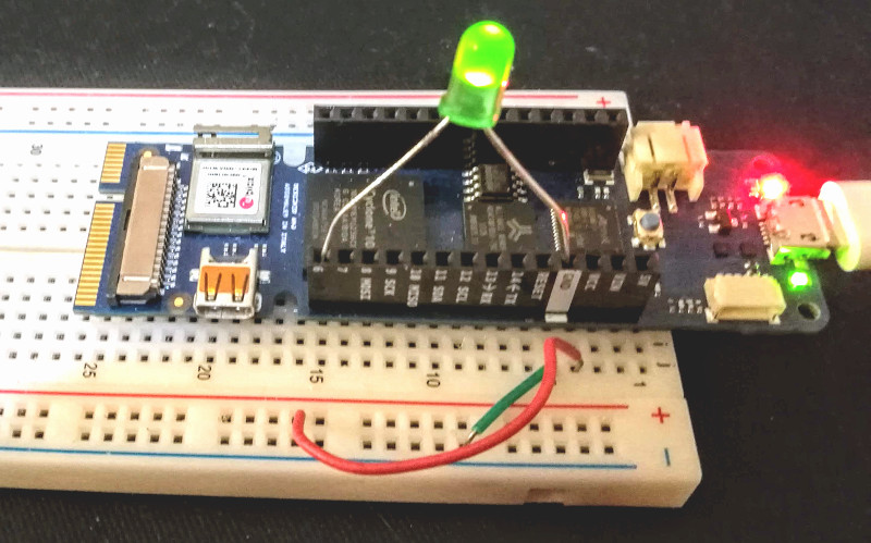
You will need an LED and dropping resistor on pin 6 unless you want to watch with a scope or a meter. I always keep some LEDs with built-in 5V dropping resistors handy, and even at 3.3V it was plenty bright. With one of those, you can just stick the wires right into the header socket on the board. Don’t try that with a regular LED, though!
Once you run the sketch, you can open the serial monitor or any terminal at 9600 baud. There will be a message saying you can press any key to change the blink rate. Of course, since the serial monitor doesn’t allow you to press keys exactly, you’ll have to enter something and hit enter (set “No line ending” at the bottom of the monitor screen), but on a real terminal, any character press should do it.
The main code is pretty simple:
void loop() {
static int oldstate=-1;
static int linect=0;
int state;
if (Serial.read()!=-1)
  {
  FPGAVal=FPGAVal==HIGH?LOW:HIGH;
  digitalWrite(SPEED,FPGAVal);
  }
state=digitalRead(FPGALED);
if (state!=oldstate)
  {
  Serial.print(state);
  if (++linect==16)
    {
    Serial.println();
    linect=0;
    }
  oldstate=state;
  }
}
In the loop, if serial data appears, we just toggle the output going to the FPGA. We also sample the LED output on every pass. If it has changed from the last time, we write the new state to the terminal and then update the state so we don’t flood the screen with repeated characters. A lot of the code is just tracking when we’ve written enough to start a new line.
Vidor’s Hello World
I wanted to get everything you needed in one place and an example that would be easy to follow yet show the critical working parts. It would be easy enough to use the shared I/O pins to do SPI, for example, and then you could trade data with the FPGA quite easily. Don’t forget there’s Arduino IP (intellectual property; sort of library subroutines for FPGAs) in the IP directory, too, if you want to use it.
Now you just need a project idea that makes sense for an FPGA. Our personal favorite would be a logic analyzer. The CPU can talk to the PC, set up triggers and then let the FPGA do the dirty work of finding the trigger and storing data as fast as possible. If you want something less ambitious, it is very simple to create totally autonomous PWM outputs on an FPGA. We could see this being handy for robotics or machine control where you want a very rapid sequence of outputs without CPU intervention or overhead.
Of course, not every project has to make sense. If you are just wanting to learn about FPGAs there are plenty of projects you could do with a CPU but are easy enough to build in an FPGA (the classic traffic light comes to mind). Of course, with the Vidor you have an opportunity to use a blend of FPGA code and CPU code, which is kind of the point.


Good intro to the board, thanks.
After reading all of that, I honestly can’t imagine why I’d bother. This Vidor seems like it inherited none of the expected simplicity of an Arduino, and instead just layers more BS on top of the already funky toolchain of an FPGA. That business about the microcontroller and FPGA fighting over IO pins bothered me in particular.
Most people here don’t have problems that need an FPGA. And if you do have an FPGA-class problem to solve, is there any reason to use a Vidor instead of one of the myriad FPGA dev boards that already exist?
Exactly. I really can´t see how it will enable existing Arduino user to develop things with FPGA.
And for those who already have some experience with FPGA, why would they use that clutter at all, really ?
It´s a foreseeable fail.
I agree with you dahud, it is not a good way (or low cost way) to get into the fpga world but I will say that once people start creating drivers for it (IF they do) it will be pretty awesome.
Agree, it’s a bad design and the added software complexity it brings doesn’t do anyone any good. It would be a bear to use in a real application with such crippled I/O. Overall it reminds me of the el-cheapo throw away eval boards Arrow sells.
There are much better and cheaper FPGA boards out there if you just want to play with FPGA’s. The one that Grant Searle uses for his designs is pretty good and can be had on Ebay for about $20.00.
A few years ago Max II boards were basically just shipping costs.
and max 2 is pretty much a fpga despite being sold as cpld for most intents and purposes.
Spot on. I have a few Max II boards and work fine.
BTW another option I came across is the GnarlyGrey board. $14.00 and based on the Lattice UltraPlus FPGA. All you need is a micro USB cable and some .01 male headers and you’re in business.
Perfect for breadboarding.
Yet another “I agree”.
They could have at least put a JTAG connector on there. Those with FPGA experience aren’t going to bother with it so only noobs will be writing “libraries” (HDL) for it.
I think the value proposition… If it materializes… Is either advanced people writing tools for non FPGA people or someone making a more intuitive IP composer. But yes like it is that’s only going to serve the first group.
In all fairness, any time you hook two devices together this could be a problem. Especially when both devices can be configured to drive out read a pin.
This is probably an Intel design with an Arduino logo. They’ve done it in the past and these kind of products only exist to say they are exploiting a niche / untapped area, the interest will die off once the project managers find a new useless thing to make and the sales numbers aren’t justifying a 3rd or 4th production run. Intels pretty desperate to work its way back into and ontop of the MCU market, they’d also love to get more people buying FPGAs. They don’t mind using ARM to do both of those things.
I wouldn’t be too surprised if the next Intel with an Arduino logo is a indirect competitor to Raspberry Pi, little ARM SOC + FPGA board, Match the Pi pinheaders, chuck in some uno headers, a gig of ram, hdmi out, basic ethernet and or wifi and a big mess of pins just for the FPGA along with a chunky price tag.
FPGA at Vidor has the role of adapter for HDMI output.
That was its main purpose.
FPGA programming (VERILOG) is a bonus.
Besides, why shouldn’t there be a FPGA Arduino?
Awesome Al, thanks. This board is really cool, I hope it becomes popular enough to stay around. I’ve been using the Arrow MAX1000 board recently and this looks like it’d be an easy transition.
What is the advantage here over just getting the Intel dev kit? I am mystified Arduino would make this process even worse.
AMD FPGAs? What issues does the cyclone have that you’re concerned with?
Thanks for the nice article. It’s great to see that even if we as re taking some time to release the full flow there is people like you that loves hacking and sharing. Btw we are finalizing the release of the tools that will enable recreating the libraries we released and with that enable people to modify them easily. Let me remind that the reason it’s taking so long is really that we wanted to simplify things and for those that seem not to see how we’re trying to achieve it let me remind that vidor’s fpga is basically proposed as a way to expand Cortex m0 peripherals with an infrastructure that makes it really easy to add whatever fancy hardware accelerator to your system. If you are just an Arduino user you won’t need to fiddle with RTL and just keep adding libraries to your code. For those willing to use fpga we’re providing an infrastructure that makes things easier and some feee, open source IP blocks also for stuff that used to cost quite some money, like the mipi Rx IP. Finally, the board has provision for JTAG connector but likely you won’t need it as we’re also releasing an USB blaster emulator running on the arm.
I know it’s not easy to see the full picture now as we’re taking some time releasing everything but I hope the community will appreciate our work and I’m sure platform will grow also thanks to contributions from enthusiasts such as Al.
I’ve worked with FPGAs on a hobbiest level, and they are not straight forward due to the complexity of the dev tools. This Arduino implementation is nothing short of a nightmare as it still forces you to use the same hard to use Quartus tools, and then turns around and adds several layers to get from point A to B.
The ONLY way this will work is if someone comes up with a very easy to use tool set. They really need a true Arduino for FPGAs.
Boo hiss Arduino!
Nope, we don’t force anyone to use quartus. Indeed we are even preventing use of it by providing precompiled libraries and our intentions, as I wrote, are to give Arduino users the possibility to expand microcontroller peripherals by just including a library. It’s as easy as this. For now it gets complicated only if you want to implement your own IP blocks but we never stated we would solve this…. At most we said, and done, that we would provide open source , tested IP blocks along with software drivers and examples on how to use it.
Hello Dario. Do you plan to have (or already have) FFT calculation IP block(s)? I’m wondering if it could be possible to pass data buffers to the FPGA to process FFT on them and get the output back. Thanks, Mario
Yes, that is work in progress. We’re working on an audio library that has several things in it, including fft, for filtering, delay based effects etc…
Cool, thanks! Is there a forum where this work is being discussed or specs defined/published ? I’d like to subscribe to news on this topic…
Forum is here: https://forum.arduino.cc/index.php?board=125.0
The way was https://github.com/FPGAwars/icestudio
Now Arduino is lost
Here we go again… Icestudio is a good tool and I appreciate the effort developers put in it but honestly it’s far from being as strong and powerful as native tools. Try supporting asic grade synthesis, timing closure, BIG and etherogenous fpgas and suddenly you will notice that the software will become complex. There’s a reason why xilinx and Intel are the only two real players in this field and it’s not just because they have great devices but because they put a huge amount of effort on their tools. You may not like the fact they’re closed source and incredibly big but it would be intellectually dishonest to dismiss them as unusefully complex comparing them with a toy like icestudio, that btw supports only a few devices the size of a nail compared to what other commercial tools handle.
Although I would love to see an open source toolchain for fpgas I know this can only come from vendors, at least if we’re talking seriously about the matter
What’s really irritating for me is to see all these dismisive reactions, especially when (so regular) commentators clearly don’t bother to take into account many aspects of this board and its problematics, even though that thet have largely been discussed in the comment sections of previous related Hackaday’s blog entries, even with Arduino representatives and engineers jumping in to answer precisely to various technical concerns, which is rare and great.
Yes, it has been said and debated over and over, and still Dario has the patience to explain it again, as I am : this is not a dedicated tool for electronic engineers, but more of a proposal of “programmable hardware” enhancement to the Arduino ecosystem, aiming to offer a way for most users to keep using ready-made libraries and drivers leveraging the different (powerful) onboard chips.
The difference with similar boards is that a big actor of this market, with the (proven) power to establish an actual hardware and software platform, seems, for a change, really commited to provide support for drivers developments. Even if their main focus was something like “we’ll provide our own polished integrated IP blocks so (end) users won’t have to mess with HDL stuff to take advantage of the configurable hardware”, they listened and heard the community (like Al and interested people) who wanted low-level access to make their own bare-metal FPGA programming, and are in the process of deliver just this, which is rare and great too.
That said, I want to tell you this, Al Williams : if I salute your efforts to share this particular exploration, since it is mostly based on the work of someone else, please at least NAME this person like it’s usually done on this blog, rather than this kind of vague, kind of embarassing stuff (I quote) : “If you speak french, good news, there’s some information… if your high school French isn’t up to the task, here is the Google Translate link… but I wasn’t content to just read the Google translation”, so here is your take (of the same thing)….
I don’t know him at all, but you can’t ignore than this (french) guy has, for some times now, been very active in obtaining the required informations and files on the dedicated Arduino forum, prior to publishing the very first available tutorials (while in french) last september. It just takes a few seconds to find that the name is Philippe Boudot.
Many thanks to him for this particularly useful involvement (and the good news is he was even able to let several comments, in a perfectly readable english, right after your previous article on the matter, if you didn’t notice).
Well I’m sorry you feel that way. I don’t think anyone reading it with the link and the detail discussion of what was changed would have thought for one minute that I was saying this was original work and I’m surprised you did. As I mentioned in the article what I did do was breakout the user part of the verilog and create a much simpler fpga example that directly supported people who already know hdl. I also replaced the Java program so people didn’t have to install the latest Java just to run a 5 line script. And I put it all in a GitHub repository so you didn’t have to go download from three or four different links it could be kept up-to-date. I ever forked the original code to make absolutely sure that nobody thought I had just produced that out of thin air. Okay granted I didn’t name someone in particular but I would think between the links the commentary and the git chain it was abundantly clear. Kind of how open source stuff works.
Thanks for your answer, I still haven’t study your presentation further because I was unhappy that you failed again to name this foreign blog’s author, one you already refered to previously in the same rather anonymous way. I’m sorry you feel like justifying so thoroughly the simple omission of a rather basic courtesy. Open source surely works a lot better when credit to similar work is given, and usually it is standard practise on Hackaday (and historically in the scientific field) when referering to some original work, even if it is to improve on it, even quite differently and presumably better, and your message summarize this well.
Now, regarding the very dubitative reactions about this “FPGA” solution and its problems, I understand most of them, but as the conceptors and manufaturer seems to show interest in our advices, I would prefer a more constructive approach like telling in which ways it could be improved.
Hi malak,
Thank you for your nice words. I totally agree that constructive feedback is the best way to go and I’m really open to listen, as you also probably noted by looking at the arduino forum. Unfortunately it seems like some people reading hackaday just don’t like Arduino because it is lame, because it’s too simple or any other reason that just doesn’t take into account the simple fact that we’re trying to allow use of complex stuff to people that would never even have a chance to get in touch with it. Yes, there are extra layers of software and yes, there are things you could optimize more if you know what you’re doing but no, we don’t force anyone to use our software and if you really want you can even wipe out our bootloader and program bare metal on our boards.
Having said this I know some people will still dislike what we do, probably without even having ever dug deeper on Arduino philosophy but it’s fine.. probably those guys think it’s better teaching a first time biker with a reckless downhill descent rather than starting with trainer wheels on a flat track. Maybe they’re right and some people will learn faster but we’ll keep going our way while we see that it produces good results on most people.
Regarding your discussion with Al I think every contribution is good and although Philippe wasn’t explicitly named his work was clearly referenced so IMHO there’s no bad intentions here. Again, anyone can be told he could do better afterwards but he did great and to paraphrase your words, let’s be constructive.
Seeing as Dario is here :)
Is there any plan to standardise an add-on board form factor for the mini pcie connector, as I would like to make one soon? Unfortunately official support was quite dismissive of my question.. Thinking of a SATA adaptor so I can do streaming of video from MIPI to SSD with CV stuff in between.
Hi, sorry you got impression official support was dismissive as I’m trying to address all questions in depth.
Right now there is no finished plan for mini PCIe add on boards. We’re looking for a solution that allows reusing also mkr pins but insertion is a bit tricky. Note that our mini PCIe interface only supports USB so no high speed lines are in there and a SATA adapter would have to go through a USB based controller.
Btw if you want to have an in depth discussion on these topics I would recommend to move it to the dedicated Arduino forum (https://forum.arduino.cc/index.php?board=125.0) where we’re capturing users inputs and where we can track discussions in a more structured way.
So first of all, huge thanks for an excellent article. I really like the idea, speaking as an ex-FPGA designer, currently BSP SW engineer.
Often in my recent work as a SW engineer, I find that I’m missing an FPGA honestly. Not so much for the actual functionality as much for increased testing flexibility, especially if we’re talking automated testing. This is where Vidor would shine. I think it could be used as testing equipment quite nice and also could be used for fast “small-module” bring-ups quite efficiently. Not to mention production testing. It is also relatively cheap… I really see no downside, except that the IDE, as with all FPGA devices needs to mature a bit.
Now I’m not sure why there are so many negative comments – I guess people are still afraid of the FPGAs, since they seem to mention “funky IDE”, issues with Arduino conversions, saying “real” FPGA designers would not touch Vidor… I guess none of these guys had any experience with FPGAs, otherwise they would know how it goes with Altera (I’ll never say Intel :) ). I’ll just say this – you need to send at least one service ticket to Altera in order to be called “FPGA designer”. Those that know SOPC Builder and how Qsys behaved in the beginning will know what I mean ;) And I think it would be quite an interesting device for “real FPGA designers”.
Just my 2 cents…