Translating rotary motion to linear motion is a basic part of mechatronic design. Take a look at the nearest 3D-printer or CNC router — at least the Cartesian variety — and you’ll see some mechanism that converts the rotation of the the motor shafts into the smooth linear motion needed for each axis.
Hobby-grade machines are as likely as not to use pulleys and timing belts to achieve this translation, and that generally meets the needs of the machine. But in some machines, the stretchiness of a belt won’t cut it, and the designer may turn to some variety of screw drive to do the job.
Lead Screws
We have all seen CNC projects where the builder has built a linear actuator from a length of hardware store threaded rod. Chopped to size with a hacksaw, held in place with a couple of bearings, and attached to a stepper with a coupling of some type, these screw drives do a decent job of producing linear motion. But it’s far from a perfect solution, mechanically speaking.
The main problem with this arrangement is the thread profile. As we mentioned in our post on screw threads, the V-thread profile on threaded fasteners is optimized for providing a high axial clamping force and a “non-overhauling” property, or the tendency for the fastener to self-lock. This requires a high friction arrangement, which is not optimal for a screw drive.
Ltd.
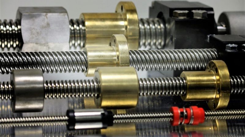
A lead screw, on the other hand, has a thread optimized for reducing friction. Lead screws commonly use a different thread profile such as the trapezoidal Acme profile. Also, the lead of the thread, or the distance along the screw’s length that one full turn of the thread covers, tends to vary more in lead screws than with threaded fasteners. Precise positioning and non-overhauling can be obtained with a shorter lead; long lead lengths will allow the lead screw to translate fewer rotations into longer linear travel. Lead screws also differ from threaded fasteners in that they often have multiple starts. Each individual thread is called a start, and lead screws often have two or more threads nested together along the surface of the screw.
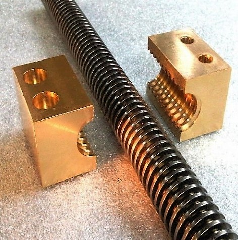
Every screw needs a nut, and lead screws are no exception. The lead screw nut is a part with an internal thread that mates with the lead screw’s external thread, and provides some way to secure the nut to the machine and transmit the force produced by the rotation of the lead screw. Because the mating surface of the lead screw and nut tends to be much longer than would be the case for a threaded fastener, a lead nut tends to be made from materials that will reduce friction as much as possible. Bronze is commonly selected for its natural lubricity; sintered bronze is often used too since it can be impregnated with lubricants. Plastics are not uncommon, although they can limit the loads that the lead screw can handle.
Ball Screws
While lead screws deliver great performance for many applications, they are not without their disadvantages. Their main downside is mechanical inefficiency. A lead screw typically converts 20% to 80% of the applied torque into linear thrust, with the rest wasted as frictional heating. This heating can lead to another disadvantage: limited duty cycle. If you’ve ever run a nut along a threaded rod by spinning the rod in a drill, you’ll get an idea of how much heat can be generated by a lead screw. The heat can easily damage a lead nut, especially a plastic or composite one. So most lead screws have a limited duty cycle, to allow heat time to dissipate.
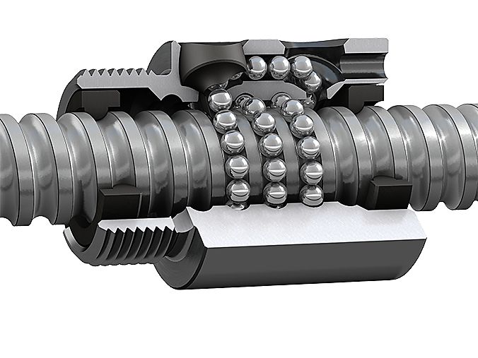
Ball screws are a different beast. They look similar to lead screws — a threaded rod with a nut — but function completely differently. Where the lead screw thread profile is generally trapezoidal, ball screw threads are more rounded. The ball screw nut also does not mate directly with the ball screw. Instead, the threads cut into the ball nut form circular channels which are filled with a line of small balls. The balls transmit force between the ball screw and the ball nut and are forced along the thread channel to a return channel, where they are delivered back into the thread channel for another trip.
The return path for the recirculating balls can be either internal or external. External return nuts have a small tube or tubes that channel the balls back into the interior of the nut, while internal return nuts have channels that are machined right into the nut body. Internal return nuts therefore tend to be larger than external returns. Like lead screws, ball screws can have multiple starts, in which case there will be multiple ball chains, and multiple return channels.
This recirculating ball mechanism is the key to the ball screw’s efficiency over the lead screw. Where the lead screw has a long path of sliding friction between the nut and the screw, ball screws experience only rolling friction between nut and screw. Greater efficiency means reduced power requirements, and reduced friction means that limited duty cycles are less common with ball screws, some even being rated for continuous duty.
One Screw to Rule Them All?
As for accuracy, ball screws generally have the edge over lead screws thanks to reduced backlash. The ball nut can be preloaded by splitting it into two separate pieces that are pushed apart by a spring; this forces the balls to jam in the channel and removes the slop from the system. A similar approach can be taken with a lead screw, but the lower inherent friction of a ball screw makes the increase in friction due to preloading less of an issue than in lead screws.
While ball screws have higher load ratings, better positional accuracy, and higher efficiencies than similarly sized lead screws, they’re far from perfect. Ball screws are much more expensive to manufacture than lead screws, owing mainly to the precision machining needed for both screw and nut. They also tend to not be self-locking no matter the lead of the screw, which might mean some applications will require a mechanical brake. Ball screws also are limited in translational speed by how fast the balls can circulate through the nut before causing damage. Also, a ball screw nut cannot be disengaged from the ball screw like a lead screw can if it has a split nut or half nut, which is important in threading operations on lathes.
The design choice between ball screws and lead screws is complex. Ball screws cost more up front, but they tend to deliver better accuracy and lower maintenance costs in the long run. Then again, the positional accuracy and increased load handling of ball screws may be overkill for some applications; in such cases, a lead screw may be fine. Then again, the increased friction of a lead screw might mean that the motor driving it will need to be upsized, and the lower duty cycle of the lead screw might be an issue.
[Featured images: ABSSAC, Ltd., and Helix Linear Technologies, Inc.]


What about threadless ball screws?
https://www.thingiverse.com/thing:125529
Bad dreams – is what you get, when someone see it as alternative.
Horrible accuracy, low torque before slip, good luck with low cost machining it.
Maybe the printed ones. We use them all the time at work for traversing operations for spooling product, etc.
http://www.okcoil.com/
Sure, but the feedback is external, and the torque isn’t large, right?
Whoa, the variable pitch is an interesting feature.
It’s like a linear CVT…
What if you use that 3 skate bearings nut from threadless ballscrew with leadscrew or some leadscrew with proper pitch (and possibly proper profile)? That will not ever slip, will have no backlash and will be much cheaper to make than ballscrew while still having low friction.
Kinda like this: https://www.thingiverse.com/thing:3168121
Here:
https://www.youtube.com/watch?v=vhodLP9ws0Q
https://www.youtube.com/watch?v=kFQBhhgTe3o
These guys make some good screws and they have lots of different nuts – http://www.helixlinear.com
These guys also supply some good lead screws and ball screws with a wide variety of nuts. They machine them to spec in the UK which is always a bonus.
https://www.matara.com/products/linear-motion/ballscrews-and-end-supports/
https://www.matara.com/products/linear-motion/power-leadscrews/
They also have a handy post, comparing the two:
https://www.matara.com/technical-articles/ball-screws-vs-lead-screws/
If you use that with any considerable loading, it will eventually become kind of threaded–and very, very sloppy :C
Just tighten the preload screw and voila: you have created thread that will prevent sliping of this system.
Maybe we can 3d print some contraption that will grind the skatebearing-mating thread into the rod.
The problem with adding preload like that is that it adds friction to the system. That will create a lot of heat during rapids. You could add preload with a standard v thread the same way to get a low backlash system but again it just adds friction and heat.
I always question when someone says no backlash, there is always backlash you can only minimize it. In this case the backlash will be determined by the axial displacement tolerance of the 608 bearings which depending on the source of bearings can be rather significant. Backlash is the sibling to tolerance, you can never get rid of them but you can minimize them at a cost and only for a certain time span as they will increase as parts wear out.
This machine was built in the 1980s, has probable been in continuous usage for decades, has ball screw slides, check out the X-axis tolerance, 0.000010″
http://cncnorth.com/ll2.html
That sounds too precise to be true. They say “resolution” not “tolerance”, “precision” or “repeatability”. That might just mean that axis moves (on average) 0.000010″ per microstep. In other words that it needs 100000 microsteps per inch. But at that microstep, it might easily wobble by 0.0001″ or even much more.
This guy tested repeatability of threadless ballscrew:
https://www.thingiverse.com/thing:298212
https://www.youtube.com/watch?v=NA_9GeFxV0o
A key point that either got missed or under-covered is backlash. The spring in the G+ teaser photo suggested I’d learn a bit about ways to manage backlash on my home machines.
They mention spring-loaded lead screw nuts like this one:
https://img.staticbg.com/thumb/large/oaupload/banggood/images/DE/0B/193e543e-0536-4672-82fe-1f0ecfc4bebc.jpg
But also go on to address how they significantly increase friction losses in designs that use nuts instead of ball-screws. Sheesh, nuts, rods, balls and screws everywhere. Why is mechanical terminology so phallic? I digress.
On a home FFF printer, it works fine. The Z axis doesn’t move fast enough for friction to really be a problem. I have some of those spring-loaded lead screw nuts on mine, and the backlash is very minimal for that application. Of course backlash also isn’t super important on a Z axis, since it doesn’t move back and forth–it goes in only one direction throughout the entire job, and only reverses once the print is done and it’s time to home the heated bed.
Unless you employ a Z hop during retractions or layer changes.
Even with a Z hop you are approaching position from the same direction every time which is what is necessary to eliminate error contribution from backlash. Just as you would on a manual mill, for instance.
Or alternatively, “why is phallic terminology so mechanical?”
Reasons. Mechanical reasons.
And then there’s the roller screw.
https://upload.wikimedia.org/wikipedia/commons/4/41/Roller_Screw.gif
Never seen one of those! What’s the coefficient of friction like compared to a ball screw?
They are probably about just as good and have a more axial stiffness but are just not very common. I dont think they last as long.
I was wondering if someone would mention those here. Roller screws are the holy grail of linear motion, except they cost a freaking ton. I was introduced to them by a buddy who had some lying around. We pulled up the datasheet and the particular units he had were rated at ~50,000 lbs.
I’m just going to quote SKF:
“Roller screws offer a performance level far beyond the capabilities of ball screws. They are well suited for heavy loads, high duty, high rotational speed, high linear speed, high acceleration (especially planetary roller screws), ultimate precision and rigidity, and for operation in harsh environments.”
My little CNC lathe has those, the first time I have ever seen them.
Would a linear magnetic motor that would, be able to replace those systems with grater precision and less vibrations, and faster ?
My initial thought is that linear actuators are like unrolled stepper motors, so movement would be quantised, and not smooth.
Linear motors can come in any form that rotary ones do. To my knowledge, most are induction, BLDC (or whatever you call it in linear form), or something akin to a stepper. The former two require feedback, and are, therefore, as smooth and high-resolution as your encoder allows. The latter is about what you’d expect, with its operational characteristics being heavily dependent on your driver.
Linear motors aren’t a straight replacement for just any linear motion system, regardless of cost. They’re efficient, fast, and very low-maintenance (with some unusual variants using magnetic levitation to completely eliminate wearing parts), but quite weak in terms of maximum force load compared to screw-driven mechanisms, or much larger for the same peak load.
Linear motor are used in some cases, the biggest downside to them is resolution. If you unwind a stepper or servo along a linear rail, your resolution is limited to the number of segments on the rail, i.e. if you wanted to .0001 resolution, you would need a very large number of segments and the associated wiring and connections to drive them.
there are linear stepper motors and then there are linear servos. I dont think I have ever seen a linear stepper in the wild. At work all of our machines we build use linear motor X-Y stages and ball screw stages for Z axis. The linear motors are dead smooth and fast with incredible acceleration rates.
Linear motors are replacing ball screws in a lot of applications, the problem with them is they have a little more squish, ball screws are stiffer. Also a screw is a much smaller profile than an entire motor track down the length of the machine.
I have seen SMD pick and place machines with linear actuators. The main PM-stator was the width of the whole machine (1,5 – 2m) and 10cm wide, the secondary on the moving arm was still 50 – 60cm long and 5cm wide. They were really fast and I am quite sure they were operated in a closed servo loop.
But for sure this machines were really expensive.
good article!
When I first read about “lead screws”, I wondered why would you make a screw out of lead?
Ah, English.
“Dearest creature in creation,
Study English pronunciation.
I will teach you in my verse
Sounds like corpse, corps, horse, and worse.
I will keep you, Suzy, busy,
Make your head with heat grow dizzy.
Tear in eye, your dress will tear.
So shall I! Oh hear my prayer.
Just compare heart, beard, and heard,
Dies and diet, lord and word,
Sword and sward, retain and Britain.
(Mind the latter, how it’s written.)
Now I surely will not plague you
With such words as plaque and ague.
But be careful how you speak:
Say break and steak, but bleak and streak;
Cloven, oven, how and low,
Script, receipt, show, poem, and toe. ”
There’s several more stanzas of that poem and it’s gotta be so infuriating for ESL speakers.
Rex Nevarette (sp?) has a skit on ESL “English is a Stupid Language” that’s pretty funny, I think it’s on Youtube.
Could it have been from a time when the screw was covered with lead as a solid lubricant?
If I led you to a lead (Pb) mine would I have to lead you home as well?
These screws are not lead (Pb) they lead the nut home and back.
No, it’s pronounced as in dog lead.
There are also ball linear rod bearings. With either of these be really careful if you disassemble them, particularly large ones, or you’ll spend an entire evening putting all the little bearing balls back into operation. Don’t ask me how I know this.
Those lessons are always learned the hard way. Regardless of how many times you are told.
Some of us learn multiple times…..
Decent article. Just a tip for folks who are designing screw systems, I created an excel worksheet to calculate ball screw critical speed and buckling load here: https://engineerdog.com/2015/02/16/free-resource-ball-screw-design-calculator/
Here is another completely free calculation tool:
https://www.bornemann-gewindetechnik.de/en/screw-dimensioning-tool/
Soon you will also be able to download complete 3D drawings from this site and configure your complete screw and nut.
The prices of ball scews vary tremendously wiht size and accuracy.
If you look at Ali / Ebay, then the lowly SFU1204 starts at prices below USD20.
And for that price you get more than you bargained for.
There are smaller units, but the 1204 tends to be the most economical.
Backlash compensation with (the higher accuracy) ballscrews is also done differently than described above.
They have 2 nuts which are just screwed to each other, and then fixed in relative position to each other to keep a pre adjusted preload. There is no spring between the nuts.
These can be found as the DFU (D for double nut) units. The cheap ones (< USD100) are slighly better than the single nut versions, but when you pay a bit more money for tighter tolerances these become quite good.
With all clamping / fixing methods there is a “spring”.
Preloading a bolt (steel) is making use of the 200GPa of “Elasticity”. (~20kg/mm^2 at yield ~ 0.2% Elongation)
We only talk in terms of torque (intended) because measuring the “spring force” acting on fastners – or preload is mostly nontrivial.
Preloading any opposing Ball/ roller /acme or other “nut” (fastners included) is still using a spring force, there may of course be a thrust washer, tab washer, cones, rod, cylindrical or radial coupler (or other device) providing that spring force (opposed of course by the tension or compression induced in the leadscrew itself….
Cheers.
OOwwooo,, it’s amazing. Especially the video you have shared. I have gathered a new knowledge from your content. Thank you very much.
The one thing I didn’t see in the article or comments was mention of rolled ball screws versus precision ground (rolled, less precise, but much cheaper). Oh, also didn’t see anything about tensioning the screw part of a ball screw (thrust bearings both ends). I’ve been told part of the reasoning is to reduce thermal influences.
This company has released an article on this topic: https://kiwimotion.co.uk/technical-articles/ball-screws/ground-vs-rolled-ball-screw/
They also supply ball screws https://kiwimotion.co.uk/products/linear-motion/ball-screws/