We’ve read a lot about oscillators, but crystal oscillators seem to be a bit of a mystery. Hobby-level books tend to say, build a circuit like this and then mess with it until it oscillates. Engineering texts tend to go on about loop gains but aren’t very clear about practice. A [circuit digest] post that continues a series on oscillators has a good, practical treatment of the subject.
Crystals are made to have a natural resonant frequency and will oscillate at that frequency or a multiple thereof with the proper excitation. The trick, of course, is finding the proper excitation.
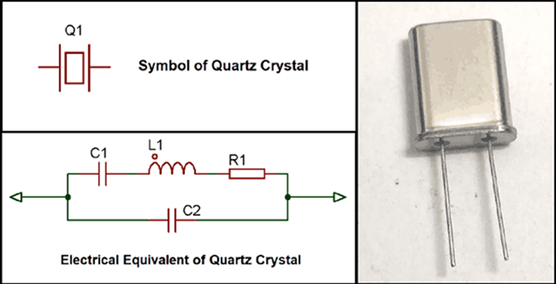
The post starts with a basic model of a crystal having a series capacitance and inductance along with a resistance. There’s also a shunt or parallel capacitor. When you order a crystal, you specify if you want the resonant frequency in series or parallel mode — that is, which of the capacitors in the model you want to resonate with the inductor — so the model has actual practical application.
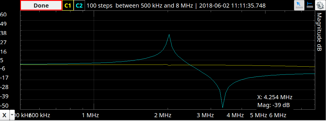 By applying the usual formula for resonance on the model you’ll see there is a null and a peak which corresponds to the two resonance points. The dip is the series frequency and the peak is the parallel. You can actually see a trace for a real crystal in a recent post we did on the Analog Discovery 2. It matches the math pretty well, as you can see on the right.
You might wonder if you could forego a crystal and just use the components in the model. In theory, yes. But the Q — the ratio of reactance to resistance — will be much lower than a crystal. A crystal is also more stable than typical resistors, capacitors, and inductors, which is why they find use where you need an actual accurate frequency. The high Q makes crystals useful in narrow-band filters, as well.
There are several common oscillators architectures, and a typical design procedure is to start with one and compute the values required. The post looks at a Colpitts oscillator. You can usually tell a Colpitts oscillator by remembering it starts with C and the feedback loop has a split capacitor (as opposed to a tapped inductor). The post also looks at Pierce oscillator and several digital oscillators. However, the post stops short of actually going through the design computations. However, it is still a lot of good information. If you can bias an inverting amplifier, you should be good to go.
You can test a crystal by injecting a resonant frequency into it. We’ve also seen SDRs pressed into service for testing.


The most important thing to know about a crystal is that it works through the piezoelectric principle, which transfers electricity into mechanical force and vice versa. The crystal is a mechanical device and really is vibrating, although so slightly that you can’t perceive it. Overdriving the crystal shortens its life.
Similarly important is knowing that it’s a mechanical resonance, and therefore has multiple modes not modeled by the equivalent circuit shown in the article. Most (?) oscillators will use the fundamental mode, but many oscillators (particularly above a few tens of MHz) will contain an additional filter circuit so that they can select one of the overtones and oscillate at that frequency instead.
N.B. the frequencies of overtones of mechanical resonators will typically not be exactly N x the frequency of the fundamental.
The crystal manufacturer will tune the overtone you specify.
This also has multiple consequences in music:
https://en.wikipedia.org/wiki/Stretched_tuning
https://en.wikipedia.org/wiki/Inharmonic
So, how much does it vibrate? I have this idea jotted in my sketchbook for years: “Decap crystal, bounce laser off it, make line scanner?”
And if that works, orient two like the mirrors in an XY galvo, and draw lissajous figures by rockbending, tweaking the series and parallel L and C to pull the crystals’ frequency. :)
One of these days I’ll find a stash of giant old ham radio crystals, the ones in the big cases you can easily open up. But I’ll throw the idea out there in case anyone has those handy.
The piezoelectric constant for quartz depends on what axis it’s cut, but regardless, you’re talking about numbers on the order of picometers to nanometers per volt. No visible deflection, but maybe interferometry?
If you ever need an excuse to learn how to properly construct an oscillator from a crystal, ditch the AVR and grab yourself a STM32.
done. what next?
Yeah, what’s the difference between AVR and STM32 in this regard? Haven’t noticed any myself. Rule of thumb 12 – 22pF and YOLO!
Years ago international crystal had a tech note on their site that went over the history of time keeping, and went over all types of scelating devices, from pendulums to atoms. One section covered how many cycles you could get out of each type of device, both if fine tuned, and in more practical conditions. Your common everyday crystal dusted the competition, as the pretty much work under ideal conditions all the time. The one take away I recall is that one pulse on crystal could ring up to million times. So a 1 Mhz crystal with one pulse of excitement could potentially ring for a second. I thought that was pretty cool. If anybody has a copy of that paper, please post it. It was an enjoyable read.
As an interesting aside, my first job decades ago, repairing telephone answering machines, the really expensive ones let you call in and retrieve your messages remotely. You had a fob you held to the phone that generated a tone, and the tone was decoded on the machine. Even though fancier ways existed to decode tones back than, these units used sealed modules with a pair of coils and a tuning fork in them. One coil would excite the tuning fork and the other coil would pick up the signal if the tuning fork moved. In their favor, they cured two problems in one swoop. They were very simple to troubleshoot and because they were electromechanical, it took them a few seconds to “rev up” so to speak, so just normal speech and background noise would not falsely trigger them. It was a very simple single tone system. I wish I still had a couple of them to play with today. Neat old tech.
I never put the 22pf capacitor in my ATmega 16Mhz projects, never had a problem. But this is not true with faster STM32 cpus. What is your thoughts ?
The AVR runs faster than the 16MHz that you would expect from the crystal. Not by very much, but outside of the +/- 20ppm that the crystal specifies.
The STM32 is a bit more finicky. if you do things properly (short traces, mount the capacitors), it works every time.
Some inductance measuring circuits use the change in frequency caused by adding an inductor to a tuned circuit. Could small inductors be measured by their impact on crystal frequency?
Crystal oscillators are one of my favorite components.
I made a video the other day of a quarz crystal in a glass envelope, like a valve (vacuum tube): https://www.youtube.com/watch?v=OKmzT0pEOPs
It was made by the Marconi company and resonates at 333.33kHz. Does anyone know how old it could be?