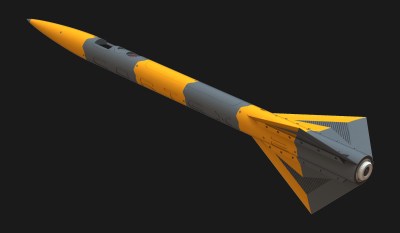
Rocketry is wild, and [Foaly] is sharing build and design details of the Cortex 2 mini rocket which is entirely 3D printed. Don’t let that fool you into thinking it is in any way a gimmick; the Cortex 2 is a serious piece of engineering with some fascinating development.
 Cortex 1 was launched as part of C’Space, an event allowing students to launch experimental rockets. Stuffed with sensors and entirely 3D printed, Cortex 1 flew well, but the parachute failed to deploy mainly due to an imperfectly bonded assembly. The hatch was recovered, but the rocket was lost. Lessons were learned, and Cortex 2 was drafted up before the end of the event.
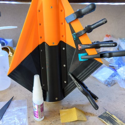
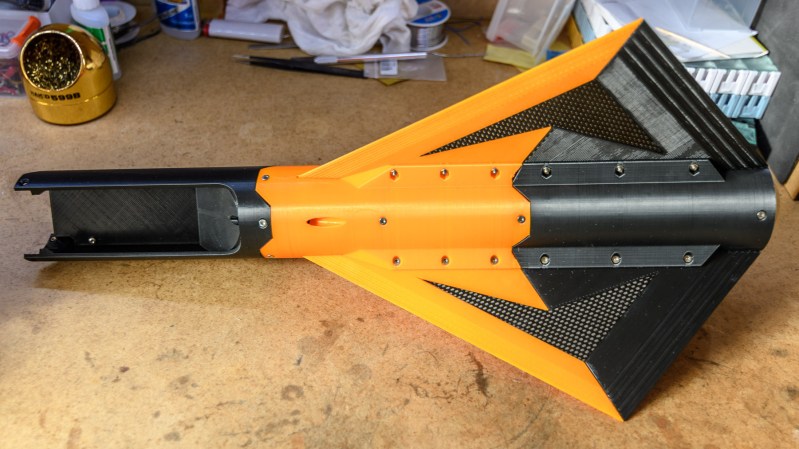
Some of the changes included tweaking the shape and reducing weight, and the refinements also led to reducing the number of fins from four to three. The fins for Cortex 2 are also reinforced with carbon fiber inserts and are bolted on to the main body.
Here’s an interesting details: apparently keeping the original fins would result in a rocket that was “overstable”. We didn’t really realize that was a thing. The results of overstabilizing are similar to a PID loop where gain is too high, and overcorrection results in oscillations instead of a nice stable trajectory.
 Cortex 2 uses a different rocket motor from its predecessor, which led to another interesting design issue. The new motor is similar to hobby solid rocket motors where a small explosive charge at the top of the motor blows some time after the fuel is gone. This charge is meant to eject a parachute, but the Cortex 2 is not designed to use this method, and so the gasses must be vented. [Foaly] was understandably not enthusiastic about venting hot gasses through the mostly-PLA rocket body. Instead, a cylindrical cartridge was designed that both encases the motor and redirects any gasses from the explosive charge out the rear of the rocket. That cartridge was SLA printed out of what looks to us like Formlabs’ High Tempurature Resin.
Finally, to address the reasons Cortex 1 crashed, the hatch and parachute were redesigned for better reliability. A servo takes care of activating the system, and a couple of reverse-polarity magnets assist in ensuring the hatch blows clear. There’s even a small servo that takes care of retracting the launch guide.
The rocket is only half built so far, but looks absolutely fantastic and we can’t wait to see more. It’s clear [Foaly] has a lot of experience and knowledge. After all, [Foaly] did convert a Makerbot printer into a CNC circuitboard engraver.


IF everything fails… reverse polarity !
Nice catch : this is indeed High-Temp resin from FormLabs. The Form2 is such a great machine!
“The results of overstabilizing are similar to a PID loop where gain is too high, and overcorrection results in oscillations instead of a nice stable trajectory.”
This is a great analogy. The software we use to check the stability of a given rocket geometry uses simpler rules (mainly upper and lower bounds on the static margin, the lift gradient, and the product of both) which I think have been determined empirically a handful of decades ago, but given the right parameters, I believe it should in theory be possible to think in terms of PID controller and check the stability in terms of gains. That would be much harder to check during the qualification process however.
Some of the bigger rockets we launch (most notably the supersonic ones) already require specific 3D fluid simulations to check the stability though, maybe the approach is similar.
What rocket motor do you plan on flying this on? Most commercial mid and high power rocket motor can have the election charge removed easily. This is a standard process for rocketeers using them with electronic deployment.
If either a reloadable or a “disposable” (Aerotech) rocket motor was used, the ejection charge could simply be left out during assembly, and the opening in the motor filled with grease to stop hot gases from the delay charge. That’s what rocketeers do when using electronic deployment.
Unfortunately, this is not always possible where I launch. These motors are delivered with the ejection charge because they are also used in another category of rockets where using the charge is allowed, and since the launch schedule is pretty tight, it is not always possible to ask the organizers to remove the charge. This is why teams are asked to make sure their rockets are compatible with the presence of an ejection charge with appropriate venting holes.
Etching PCB’s with a laser works great.. Here’s a video I made of using spray paint as etch resist and vinegar etchant..
https://youtu.be/657Jg0fUbvk
What about building a model rocket with rollerons? https://en.wikipedia.org/wiki/Rolleron To ensure they start out straight, make half circle depressions in the fin and rolleron pieces. Pins on the launcher platform would fit into those to hold the hinged rolleron parts in line with the fin until liftoff.
The launch rod or rail and airflow would keep things straight until the gyros spin up enough to make the flaps ‘lean into’ turns to help push the rocket back.
Currently in progress, been working on a flying Sidewinder/Atoll model for a while now
Have you got a link or some photos? It sounds awesome