Everyone seems to love word clocks. Maybe it’s the mystery of a blank surface lighting up to piece together the time in fuzzy format, or maybe it hearkens back to those “find-a-word” puzzles that idled away many an hour. Whatever it is, we see a lot of word clock builds, but there’s something especially about this diminutive PCB word clock that we find irresistible.
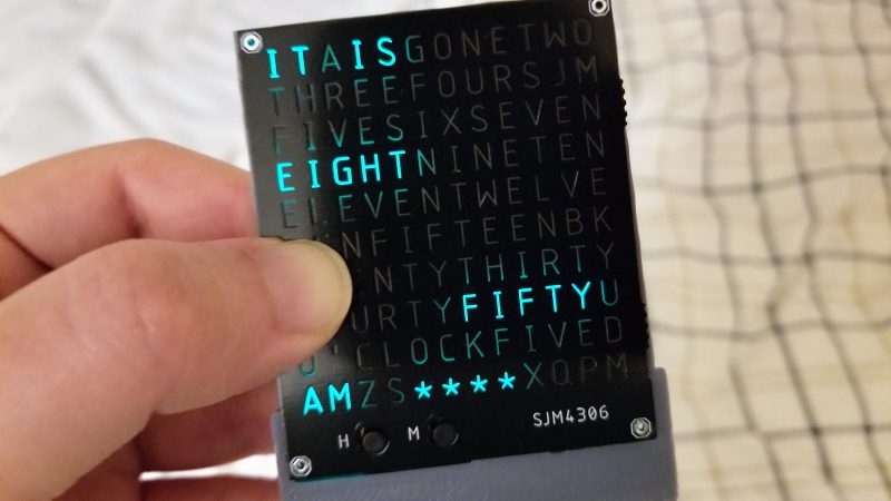
Like all fun projects, [sjm4306] found himself going through quite the design process with this one. The basic idea – using a PCB as the mask for the character array – is pretty clever. We’ve always found the laser-cut masks to be wanting, particularly in the characters with so-called counters, those enclosed spaces such as those in a capital A or Q that would be removed by a laser cutter. The character mask PCB [sjm4306] designed uses both the copper and a black solder mask to form the letters, which when lit by the array of SMD LEDs behind it glow a pleasing blue-green color against a dark background. Try as he might, though, the light from adjacent cells bled through, so he printed a stand that incorporates baffles for each LED. The clock looks great and even has some value-added modes, such as a falling characters display a la The Matrix, a Pong-like mode, and something that looks a bit like Tetris. Check out the video below for more details.
We’ve seen word clocks run afoul of the counter problem before, some that solved it by resorting to a stencil font, others that didn’t. We’re impressed by this solution, though, enough so that we hope [sjm4306] makes the PCB files available so we can build one.


Is this a kit… Nice build.
Details on kits to come soon!
When are you going to make it watch size, it has to be watch size.
Next iteration definitely. There are not many components so I should be able to shrink the design down.
On the iWatch, I wouldn’t be surprised if there’s an app for that…
I wonder who did the double sided smd work
In the first video I have a timelapse showing me hand soldering the pcb. The kit will probably just be a solder it yourself affair (the back is easy, it’s all those leds on the front and making sure they are the right way round that is a bit of a pain).
I thought from the title that the LEDs were on the backside of the PCB with the solder mask forming the letters. One PCB, not two. I wonder if that could be done, with copper on the front etched to form the letters, and very thin traces on the back to connect the LEDs.
I’ve used reverse mount LEDs diffused through the PCB substrate. They work really nicely. I suspect there might be more bleed between the letters that way though.
I’ve been tempted to do this on a multilayer board with the mask in copper hidden on layer 2, and layer 1 totally blank. Haven’t had a 4-layer project that needed indicators since I thought of that, though, and the two-layer boards I have done would have become too expensive just for a laugh.
Now that’s an interesting idea I’ll have to try out in a future project
adding lines of vias as row and columns between the characters would prevent a lot of the light from bleeding to other characters.
Is it an option to mill out the spaces between the characters, obviously leaving small bridges, to keep them all together? That should help with the bleeding. Very nice build!
We did something like that in a product, but instead of just using milled slots, we actually went with copper plated slots (0.6mm wide) to block all the light bleeding. We used reverse mount LEDs sitting in holes in the PCB, and the holes need to be countersunk from the front to allow for a wider light cone. Making the plated slots between the LEDs was a cheaper, easyer to manufacture option than trying to get the countersunk holes the LEDs sit in copper plated.
Nice idea, I’ll remember it for my future word clock ;)
When using a PCB as front cover, why not add some fancy features, like in my version? https://hackaday.io/project/27451-word-alarm-clock-with-a-touch
Wow, your word clock is beautiful! At the beginning I did think about adding touch, but decided against it for such a small clock since it would be easy to accidentally trigger buttons while holding it.
You can do it even smaller: https://hackaday.io/project/21079-word-wristwatch I also thought about a touch-switch for the whole front cover or a gyro sensor, but most of them needs to be powered up the whole time and would cost too much of energy.
Could this use a third PCB with cutouts for the LEDs instead of the 3d-printed mask? That would go well with a laser-cut acrylic case.
I’ll look into getting the midframe and possibly a nice clear acrylic case laser cut, but having another pcb as the light baffle wont work as the fr4 material is actually partially translucent.
Make them all vias! Yeah, yeah, probably impossible to get across.
Once you’re laser cutting, probably easy enough to find a material that will work, in any case.
I like this design very much, it is beautifully executed.
Yes, there is some bleed from the nearby leds on the bottom PCB. I think what you can try to alleviate the issue:
– switch to a black rubber spacer instead of printed one. The rubber can be compressed like a gasket between the two PCBs and you’ll get much better isolation between light sources.
– use a higher thickness PCB, I think up to 2.5mm thickness is not a terrible cost adder. this way if the FR-4 is leaking sideways it will need to pass more material to the top side of the board
– close a bit the solder mask opening on the bottom side. This will involve trial and error. I should be just about so that the wanted illumination of the character is not affected.
All in all, great work, keep it up