It’s time once again for another installment in “Milspec Teardown”, where we get to see what Uncle Sam spends all those defense dollars on. Battle hardened pieces of kit are always a fascinating look at what can be accomplished if money is truly no object. When engineers are given a list of requirements and effectively a blank check, you know the results are going to be worth taking a closer look.
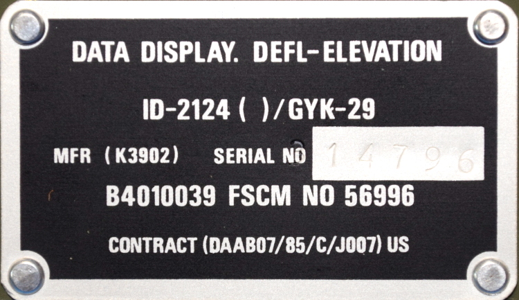 Today, we have quite a treat indeed. Not only is this ID-2124 Howitzer Deflection-Elevation Data Display unit relatively modern (this particular specimen appears to have been pulled from service in June of 1989), but unlike other military devices we’ve looked at in the past, there’s actually a fair bit of information about it available to us lowly civilians. In a first for this ongoing series of themed teardowns, we’ll be able to compare the genuine article with the extensive documentation afforded by the ever fastidious United States Armed Forces.
For example, rather than speculate wildly as to the purpose of said device, we can read the description directly from Field Manual 6-50 “TACTICS, TECHNIQUES, AND PROCEDURES FOR THE FIELD ARTILLERY CANNON BATTERY”:
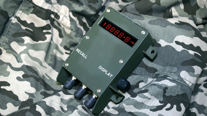
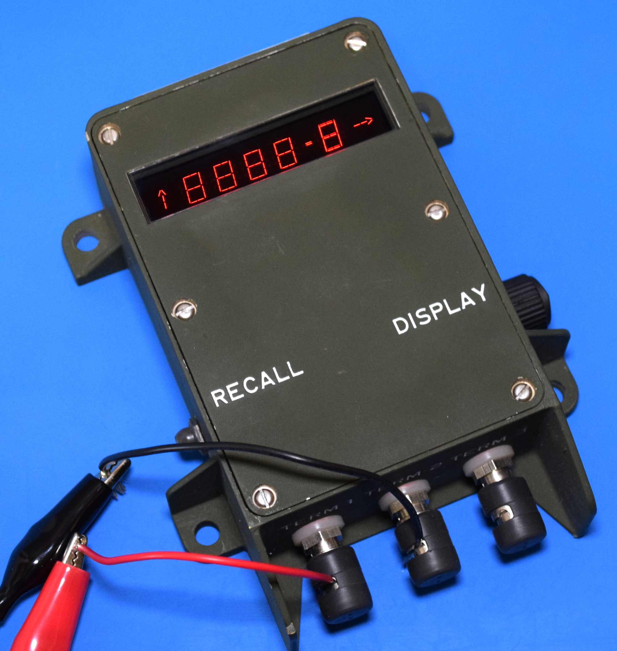
The gun assembly provides instant identification of required deflection to the gunner or elevation to the assistant gunner. The display window shows quadrant elevation or deflection information. The tenths digit shows on the QE display only when the special instruction of GUNNER’S QUADRANT is received.
From this description we can surmise that the ID-2124 is used to display critical data to be used during the aiming and firing of the weapon. Further, the small size of the device and the use of binding posts seem to indicate that it would be used remotely or temporarily. Perhaps so the crew can put some distance between themselves and the artillery piece they’re controlling.
Now that we have an idea of what the ID-2124 is and how it would be used, let’s take a closer look at what’s going on inside that olive drab aluminum enclosure.
A Veritable Fortress
All of the military hardware we’ve looked at over the course of this series has been built to meet the most stringent quality and reliability standards. Heavyweight enclosures and aerospace rated components are a given. But even still, the ID-2124 is on another level. Designed for external use in what’s likely to be an inhospitable environment, the enclosure is easily the most robust of any piece of equipment that I’ve ever disassembled.
So robust, in fact, that it actually took me quite some time to open it. After removing the six screws around the perimeter, I found the front panel remained firmly in place. As it turns out, it was also held in place with a glued gasket. This made the device impermeable to the elements, and it also did a fantastic job of keeping me out. With no way to get leverage on the recessed panel, I wasn’t sure how to proceed. I didn’t want to use heat or do anything else that might mar the surface, so this device actually sat on a shelf for awhile until I came up with a solution.
In the end, I tapped the holes in the front panel so that it would grip on screws that are slightly larger than the original ones. Threaded into the 8 mm thick panel, these screws gave me something to put some leverage on. With considerable force, I eventually broke the seal that was holding the two pieces together. While I don’t like to make any permanent alterations to the military hardware out of respect for the history involved, once the original screws are back in place you can’t tell the holes have been enlarged.
Inner Beauty Revealed
When I finally cracked the seal on the ID-2124 case and lifted the cover, I’ll admit an audible gasp might have snuck out. The board is absolutely gorgeous, and between the conformal coating and the fact it’s spent the last 30-odd years in a hermetically sealed box, it’s in pristine condition. It was literally like opening up an electronics time capsule. Although from when might be debatable; while the date codes on various components point to it being manufactured around 1987, the overall design looks closer to something from late 1970s.
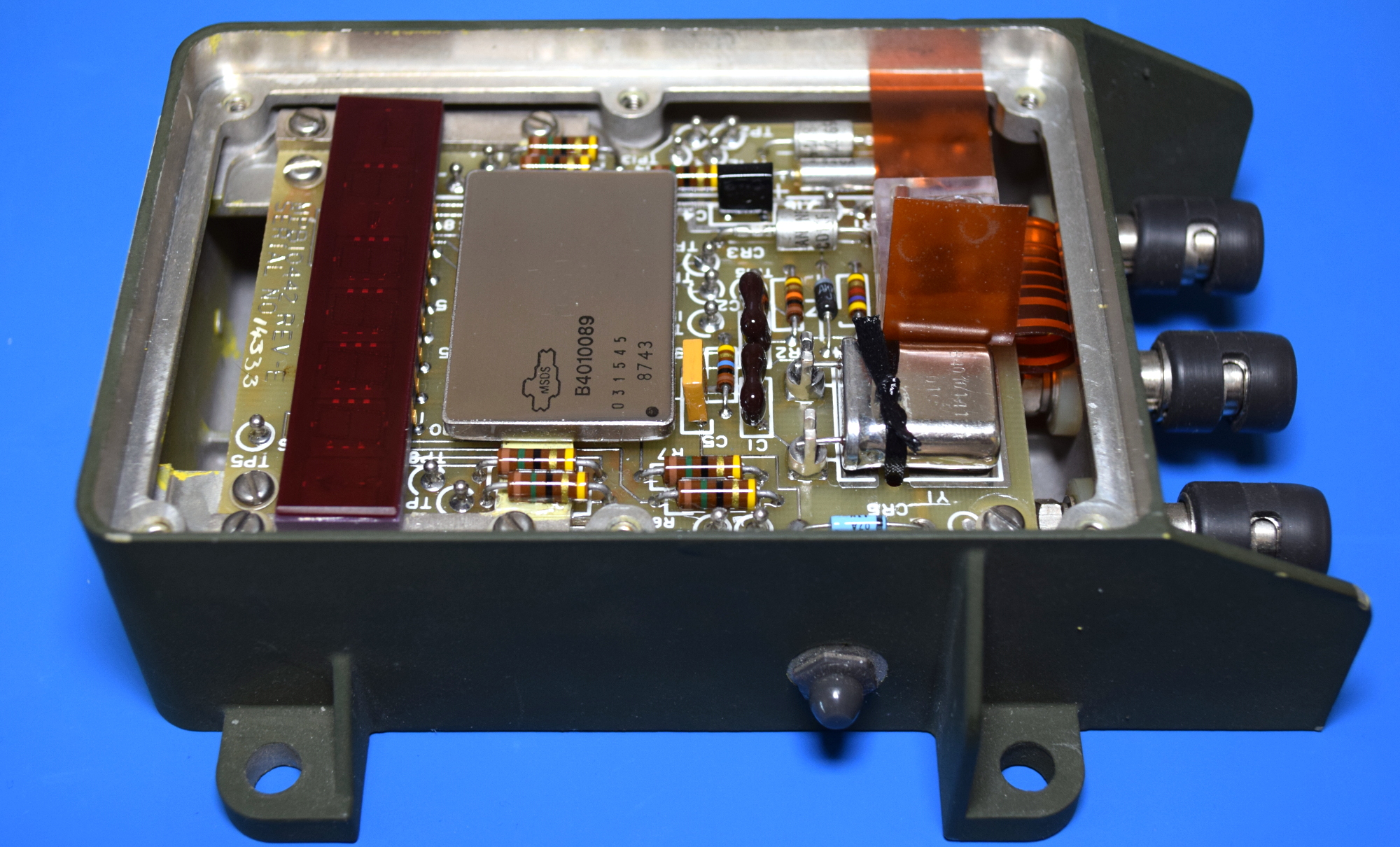
I was somewhat surprised to find that the single PCB was all that’s inside the ID-2124, the majority of the enclosure is empty space. It’s possible that an earlier version of this device required more electronics to operate, while this later version managed to pack everything into one board. Though I couldn’t find any obvious evidence of that, such as unused mounting holes in the case.
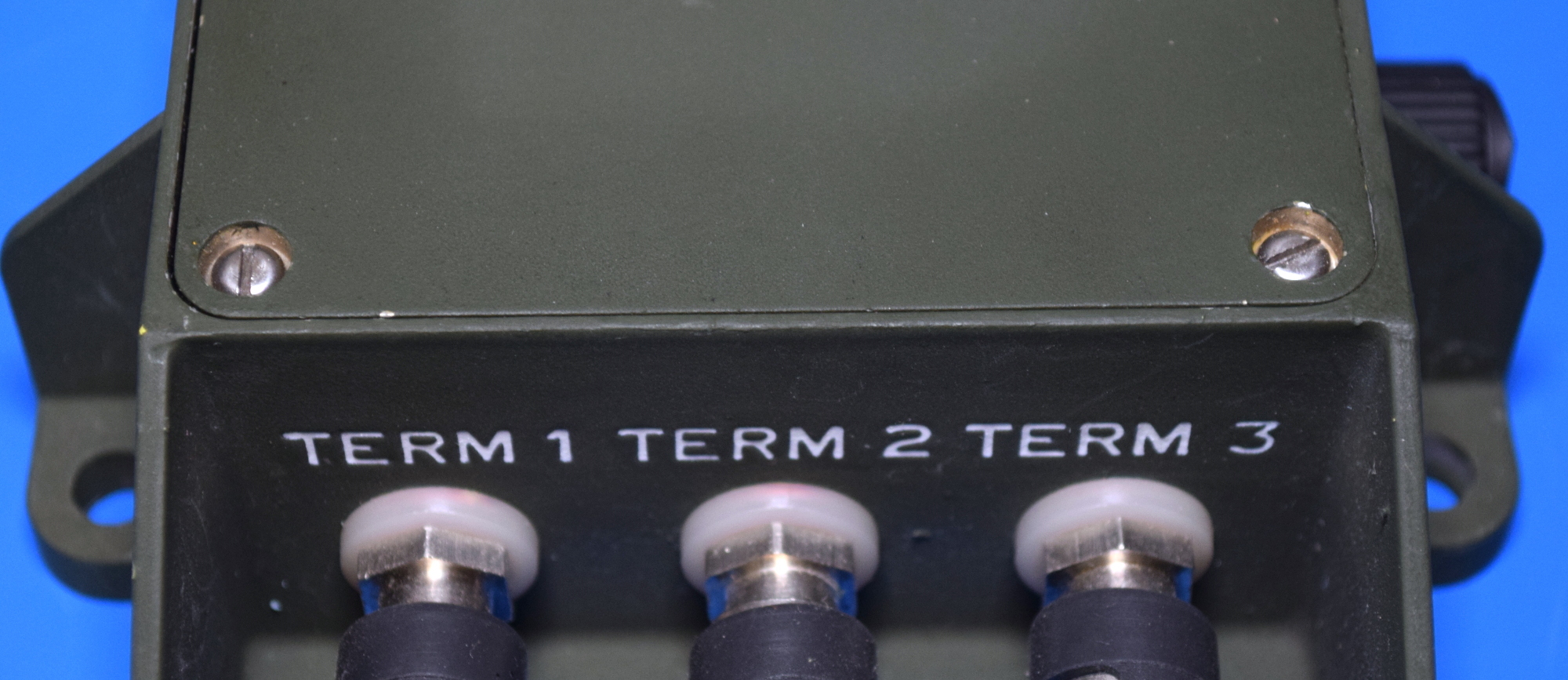
With the PCB removed, we can see the only components below it are the controls and wiring lugs, which are connected via a flexible flat cable terminated with a delightfully chunky plug. There’s also a handwritten notation that lists the Federal Supply Code for Manufacturer (FSCM), the part number for the case itself, and the current design revision.


Electronics from Another Age
The PCB of the ID-2124 is unquestionably beautiful, but also somewhat alien to the modern eye. It’s not just the nearly translucent substrate, or the unapologetic use of the dreaded square trace. Even some of the components are strange. We can identify the resistors and crystal well enough, they just look like larger versions of what we’re used to. But there’s some genuine oddities here as well.
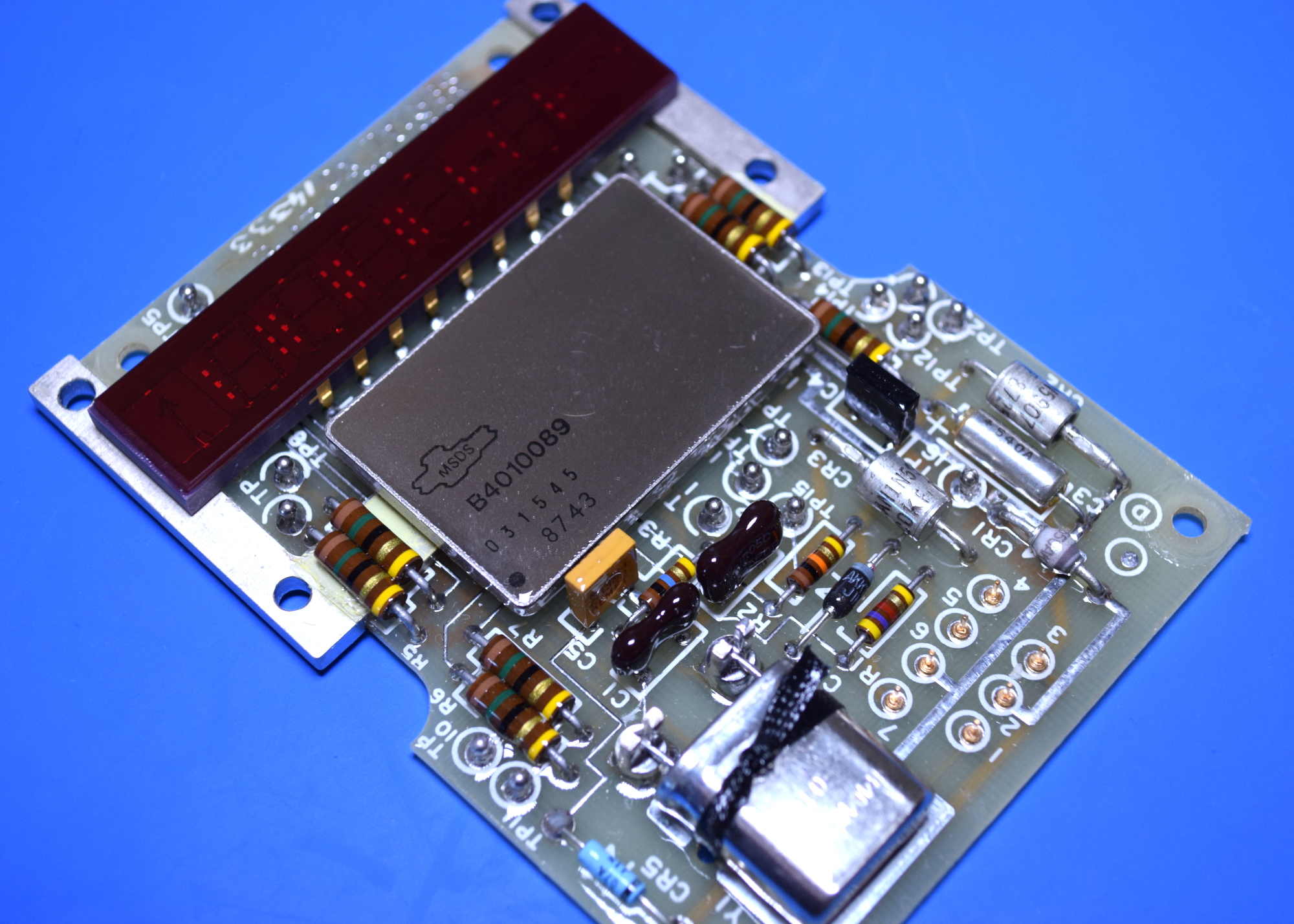
Chief among them is, unquestionably, the huge device in the middle labeled B4010089. It’s clearly a microcontroller of some type (to use the modern parlance), but I’ve been unable to find any information on it. In the diagrams I’ve found, the device is simply referred to as “LOGIC AND DISPLAY”, which seems to indicate there’s a display driver living inside that sealed metal package as well. Also note that it and the two resistors on either side have been attached to the metal bar with what appears to be a thermally conductive material. It’s probably safe to assume that this component gets rather warm during operation.
The display itself is another relic, though at least this time we can get a bit more information on it. The technical manual refers to this as the “OPTO DISPLAY #B4010133”, and a bit of searching online uncovers Plessey as the manufacturer. Given the somewhat unusual nature of the display, it would seem the 16 pin device was custom made for this application. Or at the very least, for similar military hardware.


Flipping the board over, it’s interesting to note how few pins appear to be required to drive the display. Sniffing the data passing between it and the controller chip with a logic analyzer could yield some useful information, but the aforementioned conformal coating on the board does make that sort of thing difficult. As it is, I couldn’t even get my multimeter probes through the coating to try and follow the continuity of traces.
Just Read the Instructions
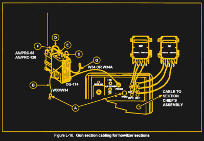 As mentioned previously, there’s actually a decent amount of information about the ID-2124 to be found in unclassified documents floating around online. Field Manual 6-50 mentions it briefly in regards to setting up the artillery piece for use, and even provides a sketch of how two of these devices connect up to the weapon’s primary “Gun Display Unit”, or GDU.
It was nice to have some context for how the ID-2124 would have been used, but unfortunately it didn’t really delve into what kind of data the unit is actually expecting to receive. Though admittedly, given the intended audience for the document, it would have been pretty surprising if it actually had that level of technical detail.
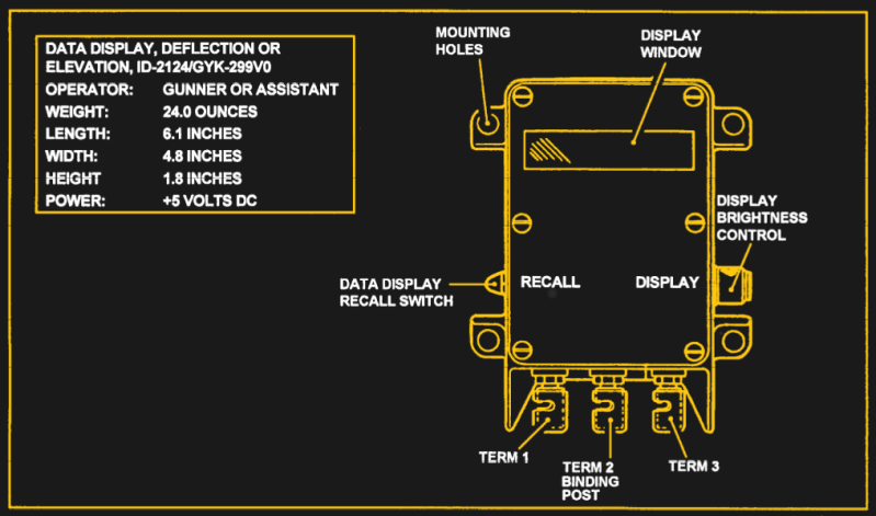
For our purposes, far more interesting information is to be found in Technical Manual 11-7440-283-40P, “GENERAL SUPPORT MAINTENANCE REPAIR PARTS AND SPECIAL TOOLS LIST FOR COMPUTER SYSTEM, GUN DIRECTION AN/GYK-29(V)”. In this document, we get a much closer look at the ID-2124, including detailed diagrams of the PCB and its components.


Unfortunately, even this document doesn’t provide any circuit schematics, and still no protocol information. Clearly the ID-2124 is a digital device, and the fact it’s connected to the GDU through just three wires helps narrow things down a bit in terms of communication methods. But without a Howitzer GDU to sniff the data from, there’s no way to know what kind of signals it’s actually waiting for.
Surprisingly Simple
 While the ID-2124 Howitzer Deflection-Elevation Data Display is certainly built tough, I’ll admit to being surprised by how straightforward the internals really were. Especially when compared to the monstrous complexity of something like the AH-64A Apache Data Entry Keyboard, which packed an Intel 8085 computer and regulated power supply into a box not much larger than this. Here there’s just a display, a control module, and a handful of passive components.
On the other hand, that might actually bode well for potential reuse of this device. Generally, the military hardware we’ve looked at has had no practical application outside of being an interesting conversation piece. But in this case, reusing the ID-2124 as a general purpose numerical display is just a matter of figuring out how to talk to it. The answer may yet be found in some arcane military technical manual, or it might even be locked away in the mind of one of our illustrious readers .


Given the Cold War pedigree I would suspect the thermally coupled resistors could be for heating rather than temperature detection.
Yeah, that’s a good point. Those resistors could actually be working as heating elements, incase this thing ended up getting used in Siberia or something.
This thing probably has a huge operating range for temperature. Probably -20-140 F. It also had to be built to handle regular impact events, and high intensity vibrations. If you’ve ever been close to an artillery barrage, you will understand that this is not a trivial event. I’m going to guess that a lot of stuff in this thing functions as part thermal battery and part structural support.
I’m also going to guess that while its case interior is unique to this system, its exterior form factor is probably very similar to its predecessor. Something to be said for a proven design, but even more about continuity. It’s very possible that the guys using this could be operating at the edge of human endurance. Sleep is very hard to find even on the friendly side of an artillery barrage. When you’ve been awake for 72 hours, actions have more to do with muscle memory and instinct than concious thought. You want to put something in their hands that they don’t need to think a lot about.
Damn you and your EM rabbit hole!
pcb and display looks very close to the Texas instrument calculator I bought in 1973
This is pretty common in military hardware, because the designs have to be locked down year (often a decade) before the design actually goes into production. In addition, most military gear is required to be hardened against EMP — you don’t stop fighting just because someone is throwing nukes around. That is likely also the reason for the metal case around the package in the dead center and the huge case — they are designed as much for EM protection as heat or moisture. I would also expect to see a lot of isolation and fusing on those three terminals coming in.
“Perhaps so the crew can put some distance between themselves and the artillery piece they’re controlling.”
No kidding, I bet it’s as loud as… a cannon blast? Not something you want too close to your ears I’d imagine.
Seriously though, I expect these units have to take a fair amount of abuse with temperature variation, moisture, dirt, and vibration at the very least.
So long as the environmental seals held I would expect the unit to operate just fine. I deal/have dealt with equipment like this, in far worse condition, and had it operate just fine.
It may be big, ugly, and heavy but it will definitely take quite a beating before it gives up the ghost.
More importantly, you want a lot of distance between you and the artillery counterfire that is expected to come back at the gun, based on radar tracking of the outgoing shells.
I busted open my AN/USM 338 Oscope and took some pictures about 10 years ago. It’s a military version of an HP1707B scope from the early 70’s and has a bunch of gold plated PCBs. Beautiful! I last used it about 5 years ago and it was still working fine.
http://mark.rehorst.com/AN_USM_338/index.html
Perhaps so the crew can put some distance between themselves and the artillery piece they’re controlling.
I doubt it, since it would be hard to turn the aiming cranks or whatever from that far away. Here’s an illustration that I think shows where this sort of thing would actually be mounted during use. There’s one (key 15 on the chart) at the assistant gunner’s position, which would have the elevation angle, and one (key 13 on the next page) at the gunner’s position, which would have the deflection angle:
https://books.google.com/books?id=1gQYAAAAYAAJ&pg=SA2-PA12#v=onepage&q&f=false
(I dunno if the pictured units are *exactly* identical to this one or not – it may not even be the right model of howitzer – but seems like it’s a similar concept on whatever model: two different fellows would use the units to read off the angles for a fire order, and then operate their controls to aim their respective axis.)
It sounds like these would be used mainly when the gun is wired into commands from a larger battery control network. I think section 7 of “Field Manual 6-50” describes how that would go:
The ‘data’ that would need to be transmitted and displayed is probably just a single number at a time (along with, presumably, a bit that turns on the horizontal or vertical arrow to show which kind of data it is).
Figure out the data format it expects, then code up a Pi Zero to send it data so that four of the digits work like a clock.
Square tracks on the pcb though :-)
Moar data:
https://archive.org/details/ost-military-doctrine-fm6_50/page/n295
Section L (page 293) covers the entire system this is part of. It’s a display for a gunner position (like Jack said, one for the gunner and one for the asst gunner) to receive digital info from the section commander, who has a keypad system that lets him coordinate the mission and show the status of all the guns in his section. There’s a case assembly on the hog that does all the real processing, and these display units are attached to that.
Your Crystal should give you a huge clue to your clock speed and your data rate. I would imagine that the third post is your data line referenced to ground, I would imagine that your signal is biased high by the same amount as the supply voltage just in case a grunt hooks the wires up wrong it won’t fry anything. Some of those resistors are probably there to bring the signal (and power) voltage down to 5v (most likely) or 3.3v. whole thing probably works off of 12v, maybe 24v or 48v, should be based on automotive battery voltages.
The case assembly unit that it hooks up to is 28v. Since it is drawing its power from the Case Assembly 28v is a good place to start.
Military vehicles are pretty uniformly 24V systems (2 12V batteries in series). The HMMWV to Abrams to a Bradley all use the same giant coaxial connector for jump-starting (a slave cable), and that is simply 24V straight off the batteries. 28V is within “acceptable max” values of what the battery should be putting out.
It’s not “acceptable max”, 12v lead acid batteries aren’t actually 12v. They’re nearly 13v when not connected but fully charged; float voltages are typically 13.2v or so, and peak charge voltage can be around 14.4v, but it depends on the voltage regulator in the alternator.
So yeah, actually, it is 28v, in normal operation. Just like a ton of big rigs
Seeing as that you have already got it powered up, it should be safe enough to start putting some digital data into the 3rd binding post to see if you can get the display to do anything. If I had to take a guess, I would suspect that the 3rd binding post has a pullup to +5v, and you drive it with an open collector output (easy enough to check, it should idle at +5v and have a few k of input impedance) with an async serial signal. I doubt they are doing any tricks with trying to encode clock signals on the power rails or using multilevel signaling, but you never know with those military guys. If you got lucky it will accept something that resembles normal async serial (start bit, n data bits, stop bit) but if you got extra unlucky it might have some sort of parity/crc bit/byte and not do anything until it sees a correctly formed packet.
As was mentioned above, you might be able to get a clue on what it does by looking at the crystal frequency, if it is divisible by 300 (1,843,200Hz; 3,686,400Hz; 7,372,800Hz; 9,216,000Hz, etc) it is a dead giveaway that it accepts a standard baud rate of some sort (300, 600, 1200, 2400, 9600, etc).
Seems insanely optimistic to think you can just shoot a ASCII UART number to this thing and something will happen. Even if it isn’t some weirdo mil comms protocol, surely there’s going to have to be some kind of handshaking or preamble that there’s no way of knowing without sniffing a valid exchange.
Yeah, the message format *might* be some character-based UART-y, teletype-y thing. But plain binary would also be sensible, maybe with some kind of self-clocking coding (Manchester, etc.). It doesn’t seem like there are very many clues either way in the visible circuitry.
And even if you could figure out the wire coding, the data format is almost certainly nontrivial. For one thing, there’s that reference to a ‘special instruction’ – which implies the existence of ‘normal’ instructions, and makes it sound like there’s probably some kind of opcode+data combination going on. Perhaps a subset of whatever protocol is used to send the complete fire orders around at the levels above.
If it is some kind of command packet or message like that, there might be not only checksums/bits expected in it somewhere, but also length info, arbitrary preambles, etc. You *could* try to send a bunch of random data and see what sticks – maybe wire something up to the display lines and automate it – but there are likely to be a lot of possibilities to run.
Better bet might be to crawl around and see if there’s one or more MIL-XXX specs that could shed some light on it. I know things like RS422 are incorporated in there. Maybe there are also specs for some kind of 1-wire digital signaling that’s era appropriate. And/or some kind of command message protocol for use on digital radio and wire links. If you could get a handle on the message format, it would at least narrow down the number of combinations you’d have to try.
More likely it’s MIL-STD-1553, a serial protocol, but definitely NOT serial ASCII. See: https://en.wikipedia.org/wiki/MIL-STD-1553
Given the use I’d also expect the paint to be chromate based (carcinogenic) and use of cadmium plating on certain parts. Nothing too concerning but I would wash my hands after touching.
We had a saying in the Navy as an ET, If it’s broke throw it overboard, If it floats you have to fix.
Hm, As a retired artillery guy, let me offer a little insight…
These units are the “universal” display components of the GDU (Gun Display Unit). They were mounted to the howitzer near the gunner and assistant gunner’s positions. They normally displayed 4 digit numbers, mils of deflection or quadrant elevation, or 5 digits with a decimal were displayed in precision fire missions.
The binding posts are used to support field repairs. ANY wire can be used to connect these to the central unit on the gun, which also connects to a much more complex device for the gun chief.
The AN/GYK-29 referenced above was the Battery Computer System (BCS), a (for the time) sophisticated fire control computer which received fire mission data (target location, etc.) and calculated firing data using the location of each individual gun in the battery, computed individualized firing data to allow dispersed guns to converge fire onto the target.
Elements in the “gunnery problem” the BCS solved for each gun to target data set included: gun location, target location, wind direction, wind speed, firing propellant temperature, muzzle velocity variations (to account for bore wear), curvature and spin of the earth, shell weight and ballistic characteristics. I’m probably missing a few as I’m working off 30 year old memory.
This resultant firing data was transmitted (originally over field wire) to the Gun Display unit, which broke the individual elements into the relevant display units for the gun section chief and crew.
This system evolved over decades, beginning in the 1950’s and continues to date. I would be surprised to find that the display unit you have dissected is not still in use, under the “if it ain’t broke”….. principle.
An incomplete, but public reference is here: https://en.wikipedia.org/wiki/Gun_data_computer
An interesting take away from this article is that relatively few of some of the original components survive, due (according to this article) to the inclusion of hazardous materials in their construction. Some of the earlier computing units also contained significant amounts of gold, and I cannot imagine that they were not recycled for those purposes.
Artillery officers of my era were taught to solve the gunnery problem manually, using tabulated data, charts, analog computing devices (think slide rules) and precomputation of corrections for met data, etc., within ~30 seconds of receiving a target location, using a fire direction crew of three or more. The BCS could crank out more accurate data for all 6 guns in the battery in around 10 seconds.
Hope this helps……
I’m also an ex-gunner, though a ‘less-vintage’ example than WhiteB0rd. ;-)
Given that the display is for both elevation and deflection, what you can expect is that it display numbers (in Mils) from 0 to somewhere less than 3200 (3200 mils elevation would be straight up, 3200 mils deflection would be behind you). For those unaware, there’s 6400 mils in a circle.
There *may* be the ability to display negative values, but I’ve never seen an ‘Angle of Sight’ that low as you’d be direct firing (like a tank).
Thank god. I’ve read accounts of those situations, and they are not places you want to be.
Direct Fire is the mission to which you are referring.
The scenario is that the gun or battery is being engaged at close range, i.e., the gunners can SEE the attackers, rather than indirectly, by counter-battery artillery fire or other means.
In this case, the gunners are trained to engage independently, on command to defend the battery, and themselves. You drop the tube on the deck, and fire away.
US howitzers are capable of doing so with the onboard optical sighting equipment normally used to align the piece for each fire mission, or with a dedicated direct-fire telescope.
The electronic GDU (Gun Display Unit) display we are referencing plays no role in that kind of mission.
WARSTORY: We were practicing this mission at Ft. SIll, OK circa 1987, firing 8″ (203mm) howitzers in direct fire. This was using a standard 200lb HE projectile, fused for impact, at targets about 1500m out, which was the min safe distance.
I and the Battalions senior officers and some others were observing about 100m behind the guns, when after one shot, one of us, our Battalion Medic, went “Ooff”, and went down. He had taken a chunk of the baseplate out of one of the rounds, about the size of a golf ball, straight to the junk, at 1600m distance.
The chunk was still hot.
Thankfully, no real injuries. We moved the targets to be engaged out another 500m.
Needless to say, gunners LOVE to practice this mission, under safe conditions, but loathe ever having to resort to it IRL. It’s damn near as hazardous to the gun crews of un-armoured howitzers as it is to the guys they’re shooting at.
WB
Lots en empty space in standard dimensions/slowly evolving enclosures usually means retrofit so it could be that this type of enclosure was designed a while back and the electronics, while more modern were made to be retroffitted into it without any modification.