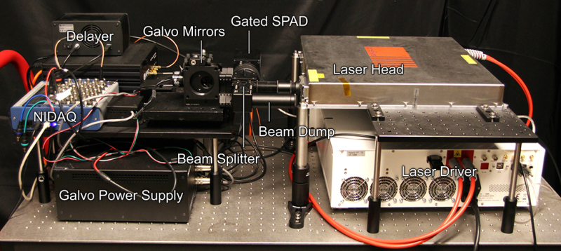
The concept behind non-line-of-sight (NLOS) imaging seems fairly easy to grasp: a laser bounces photons off a surface that illuminate objects that are within in sight of that surface, but not of the imaging equipment. The photons that are then reflected or refracted by the hidden object make their way back to the laser’s location, where they are captured and processed to form an image. Essentially this allows one to use any surface as a mirror to look around corners.
Main disadvantage with this method has been the low resolution and high susceptibility to noise. This led a team at Stanford University to experiment with ways to improve this. As detailed in an interview by Tech Briefs with graduate student [David Lindell], a major improvement came from an ultra-fast shutter solution that blocks out most of the photons that return from the wall that is being illuminated, preventing the photons reflected by the object from getting drowned out by this noise.
The key to getting the imaging quality desired, including with glossy and otherwise hard to image objects, was this f-k migration algorithm. As explained in the video that is embedded after the break, they took a look at what methods are used in the field of seismology, where vibrations are used to image what is inside the Earth’s crust, as well as synthetic aperture radar and similar. The resulting algorithm uses a sequence of Fourier transformation, spectrum resampling and interpolation, and the inverse Fourier transform to process the received data into a usable image.
This is not a new topic; we covered a simple implementation of this all the way back in 2011, as well as a project by UK researchers in 2015. This new research shows obvious improvements, making this kind of technology ever more viable for practical applications.
The obvious applications for this as noted by the researchers include things like LIDAR data processing and autonomous cars. More challenging are things like medical imaging, where one could image even that’s what’s normally being hidden by tissues or bones.
For those interested in learning more, the paper, data sets and more as presented at SIGGRAPH 2019 are available here.


Nothing new here. Polish Military University of Technology in Warsaw developed very similar technology for GROM unit back in 2007. AFAIK prototype devices were mounted on Rosomak BTRs and used by Polish Army in Iraq.
FPGAs and DSPs to the rescue.
pretty epic, looks like something that could be implemented on existing hardware and added to the toolkit for autonomous vehicles.
Maybe, but more information going in doesn’t always mean a better experience out.
The Fourier Transform is used for two very distinct purposes in these kinds of applications. First is for spectral analysis, as in a transformation from a time domain to a frequency domain and the inverse.
The second purpose is to do fast math. This is from the relation between the transform and convolution and correlation. The discrete Fourier transform (DFT) done with the FFT algorithm makes correlation and convolution much faster.
It would be nice if HaD could always make it clear why FFT or Fourier Transform is mentioned – as is done here fairly well.
P.S. I would call this a flying spot scanner in which something (a wall?) makes up the sensor for reflected light.
I should have watched more of the video first. The processing is plenty complicated. The time-of-flight windowing plus the scanning must produce a bunch of slices, and they are not flat(?). Then a space filling data set that is deconvolved in some way. From the comment about the LASER being 10,000 times more powerful as last year, one can assume it is pulsed, and the pulse is short and is used to get the time slices and does one or more pulses for each position of the scan. Lots-o-Data.
I’m thinking a step in the processing algorithm that has characteristics of different materials optical properties (probably predicted to aid in processing time), and maybe electromagnetic properties so having molecular energy components data, so to know effect by the source transmitter might better tune to resolve the image more clearly. Really awesome work!
This uses a single scanning detector, kinda the Nipkow disk of 3D imaging. The obvious next step is to have an array of SPAD detectors to do the job more efficiently (and faster, if processing can keep up).
Though I’m sure they used a high-performance single detector, full-blown SPAD arrays exist, and some are even cheap, like ST’s VL53L1X, with its 256-element array, costing just a few dollars. First Sensor, Hamamatsu and e2V all make commercially-available arrays that could work. e2v, in particular, makes megapixel arrays that could collect data thousands of times faster than the single-scanning-pixel approach.
So when the -1th law of robotics (superior life must replace anachronistic life) is understood by AI driven robots, they will be able to hunt us down from around corners, not even presenting us with a target to shoot back at. :-) (wearing sarcasm hat)
Die Menschenjaeger. They can wait for centuries disguised as a rock.