For any sort of precision machine, precision adjustability is required. For the hacker this usually involves an adjustment screw, where the accuracy is determined by the thread pitch. This was not good enough for [Mark Rehorst] who wanted adjustment down to 10 μm for his 3D printer’s optical end-stop, so he made himself a differential adjustment screw.
Differential screws work by having two threads with a slightly different pitch on the same shaft. A nut on each section of thread is prevented from rotating in relation to the other, and when the screw is turned their relative position will change only as much as the difference between the two thread pitches.
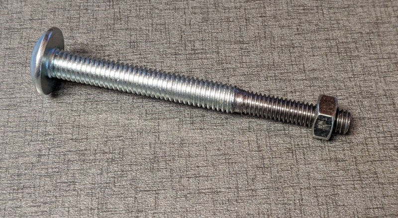
The differential screw in this case started life as a normal M5 bolt with a 0.8 mm thread pitch. [Mark] machined and threaded section of the bolt down to a M4 x 0.7 mm thread. This means he can get 0.1 mm (100 μm) of adjustment per full rotation. By turning the bolt 1/10 rotation, the relative movement comes down to 10 μm.
This mechanism is not new, originating from at least 1817. If you need fine adjustments on a budget, it’s a very elegant way to achieve it and you don’t even need a lathe to make your own. You can partially drill and tap a coupling nut, or make a 3D printed adapter to connect two bolts.
Fabricating precision tools on a budget is challenging but not impossible. We’ve seen some interesting graphite air bearings, as well as a 3D printed microscope with a precision adjustable stage.


“two treads with a slightly different pitch” Spelling of threads (not a nitpick– important word for search here)
Whilst we’re on the topic of nit-picking… “By turning the bolt 1/10 ration, the relative movement comes down to 10 μm.” Are we rationing screw turns now?
Fixed, thanks!
On the animated image: “Tiny adjustment can be made to the crean block due to the thread pitch differences.”
Crean block? Is that an actual thing, or should it say ‘green block’?
The second nut on a differential adjustment screw now has an official name.
So it is written, so let it be done!
I’ll update the Wikipedia page ;)
Obviously the Crean block was invented by a Jobadiah Crean when he tried to screw twice at once.
Also, you can reverse the pitch ratios if you want to make faster, larger adjustments!
I think it would have been much easier to glue or weld two bolts threads to threads and then cut the head off the smaller bolt than it would be to machine new threads. But then again, I’m a software guy not a machinist.
It’s much much easier to keep the threads coaxial by cutting them both in a single setup.
Glue or welding may work but getting the concentricity to where the second shaft is not offset is a challenge.
See the following at about 1 minute in: https://www.youtube.com/watch?v=WTAydtc2t6w
If you don’t want to make one it’s possible to find manifold and header studs with a different thread each side. Especially when an engine block started out imperial then went into a car that was “all metric” well yah the outside is M8x1.25 but the inside is 5/16×20 or something.
Heh, think before pulling numbers out your butt RW, those are practically the same pitch. You’d want 1.5 on the metric side or 24 tpi on the imperial to see a difference.
I thought the idea was to have them nearly the same pitch so the difference between them was small.
Yes it’s under 2%, so would work for something you don’t mind spinning all day.
“serves the same size role” does not mean “interchangeable”. you’ll gall the 5/16×20 threads in the block if you put the stud in the wrong way
No, it wouldn’t. Even without a lathe, it would be near trivial to file down the threads and run a die up the “new” shaft. Alignment would stay virtually perfect. Glue would most likely fail immediately or over time, and welding would almost certainly fill in the nearby threads, necessitating cleaning them up with a die anyway AND you’d have to run one of the dies up the threads before welding so you maintain the pitch from above the weld as you backed the die back off. And then there’s maintaining alignment between the two thread sections.
So yea, simply connecting two threaded rods by welding, ok, that would be easy. For *this* application, however, it wouldn’t be the best approach.
Done that, didn’t end up too well.
Problem: it’s impossible to start the die perfectly straight. When it cuts in, it twists and bends the shaft ever so slightly. A different version: solder the smaller screw inside the head of a hex socket bolt in a carefully aligned jig. A large grub screw works the same.
Hmm that grub screw idea has merit – easy to make a block to hold the screws in the lathe square enough to thin the tip for attachment to the grub screw (I’m envisioning a 3 stage operation (1) round out the grub screw hex(seems easier than filling with braze/hexing the other bolt) (2) cut bigger screw bolt down to snug fit into the rounded part of the grub screw (3) join with loctite/braze/friction fit as you wish.)
Ideally would hex a bolt to match the grubscrew’s existing features, but that would be much easier with a mill and hex collect block etc which is more tooling needed. The way above just a lathe and some extra stock to make fixtures is needed, and should yield very good results (can also knock out say 20 of each part while the fixture is in the lathe)
And perhaps a more elegant and compact solution would be to drill and tap the end of the primary screw with the desired pitch of a differential screw inserted into it’s end, therefor not having the overall length protruding from the opposite end.
But I can see the original being useful with a captive bearing on the end, giving you a three point defined ratio adjustment mechanism. Picture an optical assembly with with three lenses, the one in the middle being adjusted at a separate ratio from the one on the end in respect to the one on the primary block. It could also make for an interesting pantograph type mechanism.
If you run the secondary screw all the way through and put a knob on it, you also get a coarse adjust knob for very little extra effort.
I’d be interested in someone putting a dial-indicator on this to check how jumpy the position is on moves.
Maybe a spring to help take out some of the backlash will help.
I like the concept though… =)
Agreed on the backlash. Standard threads have a surprisingly low thread engagement, usually around 75%. When I mill threads, I usually shoot for 95% and the parts never bind up. Unless you’d be be doing custom internal threads for the corresponding parts, you’d definitely need to address backlash.
The nuts here appear to be plastic, so it would be quite easy to have them be a bit tight and thus backlash-free.
Groovy thing to throw in the ol’ bag of tricks! That gif is great/memorable, and making one not nearly as intimidating as one might’ve imagined not having seen the real deal right with it. Cool.
Isn’t there issues with slop or play or backlash or whatever you awesome people who actually understand this stuff call hysteresis? Either way awesome thing to know about and super clever!
I wonder if you could get the optical endstop itself to have 10um accuracy, with modulated light, an ADC, and averaging?
What about a point source LED and a small diffuse reflector, such that as you get farther the power TO the reflector drops off with the inverse square, and the fraction of power from the reflector is decreased again, which would make the curve very steep, and the exponential effects might be far stronger than any linear variations in power you might get.
Perhaps an inductive or capacitive endstop would be better, the exponential dropoff of the electric field could be pretty darn precise if you did it right.
Good point, I would guess you would need some spring preload in order to make this setup work.
In ANSI you can get a rod the right diameter and use a National Fine die on one end and a National Course die on the other end. 1/4″ course is 20 to the inch and fine is 28 tpi. 5/16 is 18 and 24. #8 is 32 and 36. Check here https://www.boltdepot.com/fastener-information/measuring/us-tpi.aspx
In the case of the #8 if you go 32 threads backwards that is 1″. You also go 32 threads backwards on the fine side, which is 32/36″. Motion of the moving block is 4/36″. Or for one revolution: 4/(32*36) = 1/(8*36) or 0.0039inches per rev. Also 1/256 of an inch. Now that is mighty handy in micro-controler math. (The ever useful base 12 FTW). Somebody check my work?
OK, this is really cool and I have to go make a spreadsheet now. Funny thing is I have seen this in the ancient past and it never occurred to me how simple. They were for adjusting positions of small optical tables on a big plate.
Any stuff about flexures and fine positioning catch my eye.
I checked. 1/288. Not 1/256. Drat!
I love that, don’t need it right now, but I’ll try it very soon !
Piecutter, your solution is very interesting, but how can you prevent the lead screw to unscrew itself when going backwards, even with the red “glue” and another bolt, if there’s torque, it will unscrew. But for lightweight movements, it’s the easy way !
Comedicles, as a french, the only imperial things I know and use sometimes are the 1/4 and 3/8 standards used for the photographic gears all around the world, when I started reading your comment, my eyes got bigger and bigger, I could understand what you were talking about, but absolutely not the “maths”. Now, it’s my smile that’s big ;^D. Imperial’s not for me !
At first I was just thinking about ANSI because it has course and fine pitch for every size. (The ANSI metric is not the same as Imperial. The US adopted an inch defined as 25.4mm long ago and there are other differences.)
But the French metric has course and fine also. And most of the sizes produce smaller adjustments than the ANSI. For example 3mm bolts can have pitch 0.5 and 0.35 mm. That gives motion of 3/200mm per revolution. 4mm has 0.7 and 0.5 and 1/50mm per rev.
I like ANSI sometimes because there are so many integers commensurate with 12 (1, 2, 3, 4, 6) and only two that are commensurate with 10 (1, 5). And you can use rational arithmetic with the fractions and get exact answers with integer math.
For small backslash-free motions, levers with flexure hinges may work better and could be 3D printed as one piece. I use this tool to predict the involved forces: https://www.vinksda.com/toolkit-mechanical-calculations/calculating-flexure-hinges/
(except for sharing the first name, I have no relation to that website)
When I first saw this article, even though I’ve built some differential screw adjusters I totally thought man flexures are the way to do this. But I’d never seen tha tcalculator. That’s really useful: thank you. I’ve been printing a lot of flexures lately and this would have saved me a ton of time.
a similar concept used in a hoist, https://youtu.be/OXzGSB4i1UU
Amazing that noone here seems to know of differential screw micrometers.
They are indeed exotic, but Starret and others do make them. Here’s one from Newport motion.
https://www.newport.com/f/dm-13-differential-micrometer-heads
Kaiser boring heads I believe work this way as well.
The same principle is used for power amplification (essentially a reduction drive) in a traditional device usually called a “Chinese windlass”
https://etc.usf.edu/clipart/61400/61437/61437_windlass_md.gif