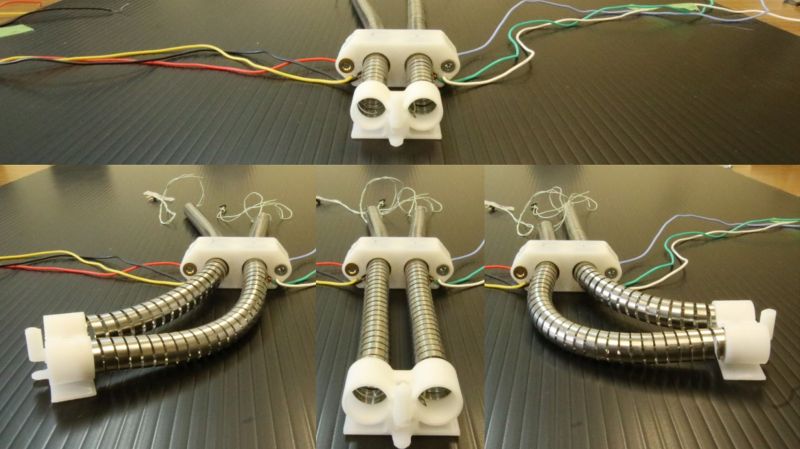
Most experiments in flexible robot actuators are based around pneumatics, but [Ayato Kanada] and [Tomoaki Mashimo] has been working on using a coiled spring as the moving component of a linear actuator. Named the flexible ultrasonic motor (FUSM), [Yunosuke Sato] built on top of their work and assembled a pair of FUSM into a closed-loop actuator with motion control in two dimensions.
A single FUSM is pretty interesting by itself, its coiled spring is the only mechanical moving part. An earlier paper published by [Kanada] and [Mashimo] laid out how to push the spring through a hole in a metal block acting as the stator of this motor. Piezoelectric devices attached to that block minutely distorts it in a controlled manner resulting in linear motion of the spring.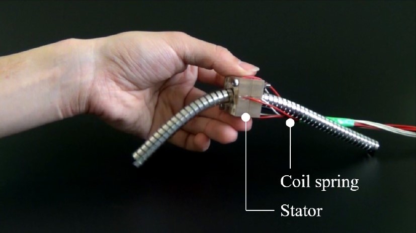
For closed-loop feedback, electrical resistance from the free end of the spring to the stator block can be measured and converted to linear distance to within a few millimeters. However, the acting end of the spring might be deformed via stretching or bending, which made calculating its actual position difficult. Accounting for such deformation is a future topic for this group of researchers.
This work was presented at IROS2020 which like many other conferences this year, moved online and became IROS On-Demand. After a no-cost online registration we can watch the 12-minute recorded presentation on this project or any other at the conference. The video includes gems such as an exaggerated animation of stator block deformation to illustrate how a FUSM works, and an example of the position calculation challenge where the intended circular motion actually resulted in an oval.
Speaking of conferences that have moved online, we have our own Hackaday Remoticon coming up soon!
[tweet https://twitter.com/AyatoKanada/status/1320949579911557120 align=”center”]


With 3 you can make arms for this: https://i.pinimg.com/474x/13/65/18/136518d458777fe27f8a299ba30d0eed.jpg
“the acting end of the spring might be deformed via stretching or bending, which made calculating its actual position difficult.”
I’m sure the mathematical equation would be interesting for some but I can’t help but feel like a tiny neural network could be quickly trained to correctly translate the information.
I never could find the ultrasonic actuators elements online (appart from PCBmotors, but it’s expensive), even the camera lens motor rings on aliexpress are a scam and they don’t actually ship.
Has anyone found DIY compatible elements online? can we recycle piezo discs in a clever way? use capacitors?
Ultrasonic motors come in various shapes, but AFAIK they are all still very expensive. (Like: $300 or more each.)
You can purchase raw piezoelectric disks on eBay: not the metal disks used in alerters, but the actual piezoelectric elements that go into transducers.
I have a couple and had it in mind to plate them with copper and etch electrodes on the surface, to see if a hobbyist version could be easily made.
Below is a link to the elements. I’ve always wanted to try this, but never had the time.
https://www.ebay.com/itm/Piezo-Electric-Transducer-Disc-50mm-Ultrasonic-Cleaner-Transducer-Repair-Kit/163444265456?hash=item260e0991f0:g:JXUAAOSwJ~xcHFjx
Thanks, that’s a step in the direction I want!
Their actuator buzz’ @ 80 kHz, 1″ piezo disk ~ 1.2 kHz. I’ve seen modes in flower dusted on the disk, with a watt or two of power, < 100 V go up to 1.2 MHz. Didn't have it on a network analyzer.
I built a crude piezo-gyro with a couple 1" piezo-disks, concentric-drilled 3/16 to fit a 2 1/2" long wind-chime beam a long time ago. I could post pictures somewhere.
I've considered drilling a piezo-disk sandwich to pump ink onto a printer filament, right after the nozzle. Probably need to etch the BaTiO:Zr for a triangular mode pattern for 3-color ink. Curie point is ~180 though.
Considering an actuator, without patterning and polling the ceramic, and perhaps etching the surface, I don't thing much power is possible off higher modes. But say, at 2 or 4 kHz, with an aptly-tuned plastic slinky?
You can hardly imagine what's in the Oobleck!
Moving state of the art for Godzilla and Alien props
I don’t want to sign up for any more email. Is this a variation on an inch-worm? https://en.wikipedia.org/wiki/Inchworm_motor
Hi all. I’m very surprised to see our robot in the article!
If you have any questions, I’ll answer them. Watch the other videos if you’re interested.
https://m.youtube.com/channel/UCHlGicJr-Tkosuc32Og-CxQ
Thanks a lot, great photos and videos.
I missed the data on power efficiency. I suspect, if you use 4 transducers, 2 W each, and have a load of 20g moving @ 60mm/S, the power efficiency wouldn’t be over a few % ?
As I peruse papers over the years for smart polymer & other actuators, I always look for the power efficiency 1st.
And the simulation software (i.e. Comsol, Matlab)?
We have not measured the power efficiency, but the power efficiency of commercial traveling-wave ultrasonic motors is about 30%. Since this motor does not optimize the friction between the stator and the slider (coil), its efficiency is only 10% at best. We used MATLAB for the simulation.
Thanks for the reply.
10%, AFAIK is pretty good then, practical for a battery operated snake or something. The math was concise and clear, so a tech school grad could follow it. I like the approximation into radial and axial components to avoid the nasty nonlinear equations.