3D printing can be great for making enclosures, and following some simple guidelines can help the whole process go much smoother. 3D Hubs has an article on designing printed enclosures that has clear steps and tips to get enclosures coming out right the first time. 3D Hubs offers 3D printing and other services, and the article starts with a short roundup of fabrication methods but the rest is a solid set of tips applicable to anyone.
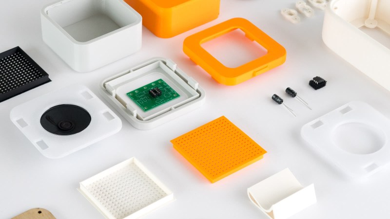
 The first recommendation is to model the contents of the enclosure as a way to help ensure everything fits as it should, and try to discover problems as early as possible during the design phase, before anything gets actually printed. We’ve seen how a PCB that doesn’t take the enclosure into account risks needing a redesign, because there are some issues an enclosure just can’t fix.
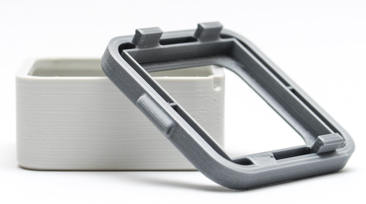
The rest of their advice boils down to concrete design guidelines about wall thickness (they recommend 2 mm or more), clearances (allow a minimum of 0.5 mm between internal components and enclosure), and how to size holes for fasteners, clips, or ports. These numbers aren’t absolute minimums, but good baseline values to avoid surprises.
One final useful tip is that using a uniform wall thickness throughout the enclosure is general good practice. While this isn’t strictly necessary for successful 3D printing, it will make life easier if the enclosure ever moves to injection molding. Want to know more? Our own Bob Baddeley has an excellent primer on injection molding, and his been-there-done-that perspective is invaluable.


1. buy a good printer
That’s crazy talk.
buy a cheap printer and make it a good printer. maker life yo!
I screwed up propper, I brought a really expensive pile of turd ($1200 AUD) printer, spent 6 months trying to make it less turd before giving it away, then bought a $400 (AUD) job and it’s been printing almost perfectly since day dot
heh for a long time i have used 1mm walls in everything because they’re easier to print, and i simply dare them to break. a few things do break but a lot of times even things that get banged around every day survive! the simple fact of the matter is that the cut-up cardboard boxes or simple globs of hot melt glue i had been using as an enclosure for so many years were probably sufficient for most projects.
and in the rare case where it is a problem, i’ve generally got a ‘wall=1’ at the top of my scad i can just change to wall=2.
OPENscad is MADE for enclosures. Parameterize EVERYTHING, and you’re done. Sort of. Copy your basic (parameterized) box, and add specific requirements for holes and bosses. For those bosses, make separate files for boards you buy, like R Pi, and include them. Before you know it, you have a style that becomes part of your brand. What a world we woke up in!
Almost any CAD system can do enclosures parameterized.
I find it easier to drill holes than edit the cad for them for one offs.
Pseudo-parametric like Fusion360 you mean? I’ll stick to “CAD-as-Code” OpenSCAD thanks! Then again you spend 3 days writing the code to fillet a corner so trade-offs! ;-)
I like to make vertical wall thickness a multiple of my nozzle diameter
I was doing that, but at least for PrusaSlicer, it didn’t do what I expected. What you want for this is to look at the “recommended thin wall” help text in the slicer and use that.
Good idea, never thought of that. There’s a tendency for gaps to show up in walls from an uneven amount of space between the perimeters. However, I think you would want to make the walls a multiple of nozzle width * perimeter extrusion width. For example, my nozzle is .4mm and perimeter extrusion width is 180%, so if the walls are a multiple of .72mm it should in theory be an even spacing of the perimeters?
Tip for making the indented pocket for pan screw heads- most of the time it makes sense to print the lid with the outside on the build plate, the inside pointing up (especially if you modeled in a lip, or the lid has side walls), which inevitably makes an overhang for your screw head pockets. Rather than use supports, which are a pain to clean out, model in a sacrificial “plug” where the pocket meets the smaller hole for the screw shaft, one printing layer thick. This plug allows the printer to bridge across the pocket and support the next layer’s smaller hole, which would have been unsupported in space otherwise. Drill out the plug with the body drill size for the screws, or cut it out with an exacto knife. The surface of the pocket is ropey from being bridged, but it gets covered nicely by the screw head.
Great idea. I’ve just been printing the seat for the screw head over air, which for small screws seems to work fine, but this might make a cleaner surface.
Much simpler:
1) model the hole for the head on the bottom, printing on the build plate.
2) add two straight bridges left and right of the bolt-hole, thickness of one layer or two. The printer can bridge these no problem.
3) either go straight to the round hole for the bolt for small bolts, or add two further perpendicular bridges.
Bolt head sunk, rests against the bridges, nothing to drill out, no support to remove.
It’s been frustrating trying to make snap together enclosures on the 3d printer. The hooks inevitably end up on the z axis, which makes them less flexible and prone to breaking with the grain of the print. Also you can’t get a sharp hook without supports, you end up with funky 45 degree angle hooks that don’t lock into place. Any ideas, success stories?
An annular snap (like a Tupperware lid) is easier, those don’t mind the 45 degree overhang, and the orientation with the z axis is right for the stress of snapping it together. Though it is temperamental dialing in the right feel, because the plastic has to stretch over the other mating part.
While you can make snap fittings just giving some registration lips for the parts and a spot for a tapping screw into the plastic, nut and bolt, threaded insert as needed is generally easiest.
For snap fittings I like to print U,Y or X shaped clips that are separate from the major case parts but snap the two together – that way printing the bit that needs to flex in the best orientation or even a less stiff filament as needed is quite easy. If the design lends itself to clips printed in good orientations I won’t bother, but its my goto when I don’t want metal parts for some reason and the desired shapes don’t want to print well.
Nice idea. It took me a couple of reads to get what it was that you were saying, but I got there
…print clips by themselves for best strength, and print parts (with locations for aforementioned clips) separately…
Good idea! Love to see some pictures. I can see that working in a few ways. You could even make an X or H shape with hooks on both ends, but one side is a permanent snap that never comes loose again, and the other end could be disassembled. Like the hook would permanently become part of one half of the enclosure.
Not sure of a scenario where it would warrant the trouble, but what if you printed the hook sticking out sideways in the XY plane, and then got it warm at the base of the hook with a heat gun or something and folded it up 90 degrees? Or the fold area was thinned down, like a living hinge?
Well the size and shapes of the clip have to be correct for what you are building so often varied. Fatdragon games Dragonlock line are a great example of x shaped clips to easily assemble tabletop gaming buildings and terrarin (Not sure but they might have been my inspiration for trying my own – been aware of them a long time now).
For most of my own clip together printing I use the U shaped over the outside edges, not exactly pretty though you can play into it design wise if that matters. But you can size it to really grip damn tight (even to the point of needing a hammer tap to apply). Yet being on the outside its easy to get that small prying tool under it to slide it off (or if its really obstinate just cut it without harming the other parts). IMO the best method for prototypes you want to survive being dumped into a box/dropped and used that can still be easily opened. If you are on to finished project casing the X and Y shapes are my favorites (H should work really well – maybe even better having that wider stance for more twist resistance – but I’ve always gone for the small center)
Another idea I’ve had but yet to use is clicking the parts together with Lego Technic pins (or possibly the two stud axles – less clamping so easier to remove but with enough friction if you size the holes right to be sufficient).
Can use them in the conventional Lego way of one clip side into each of the halves you wish to join. Or can just use the one side of the Technic pin to peg through the registration walls as done with pegged woodwork for example.
Technic pins come in a wide array of sizes and shapes now – including the two I think most useful in this situation the “half pin with stud” and “half pin with ball on the end” (the ball makes it easy to grip and pull back out), relatively small, highly consistent and are cheap to buy a heap of.
So a good method to avoid metal features and both methods of attachment should be as easy to use and cutting out the right space with the stock cutout once you have dialed in what size is really needed.
No need to thread the screw holes with a tap, you can print the thread right in!
In Fusion 360 (I know, I know. Still: for me, F360 is so insanely more powerful and easy to use compared to OpenSCAD and FreeCAD that I still rely on it), you can model ready-made threads basically with one click.
Right off the bat, the tolerances are too tight for a 3D printed thread and a commercial metal bolt, the bolt binds when you try to screw-in in. I simply apply a tiny round at both internal helical thread edges after modelling the thread, just enough to take away the edge. After slicing, this increases the tolerance such that you can screw the bolt right in without any problems.
I regularly do that for M3 bolts in all my enclosures, larger works even better.
I did a case for the Orange Pi Plus 2E. It’s had a couple of remixes, only one of which recognized mine as the source. https://www.thingiverse.com/thing:1916113
Search for Galane to find cases I did for two different CNC parallel port breakout boards and a stepper motor speed control. I also did a box to mount a common slide switch onto the cord of a power supply for white Xbox 360’s for hacking them to be high power 12 volt supplies with a switch for standby and on. Simple to cut two wires and put a switch on, but I wanted mine to look nice.
A useful thing to do with 3D printers is make dummy rounds for firearms. Just for fun I made one for .303 Savage. Chambers and extracts same as real rounds. Should make a pocket in the base for some silicone or a chunk of rubber to use as a snap cap for practice.
Not bad tips for beginners…