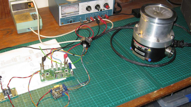
[Mark Aren] purchased a pair of Turbomolecular pumps (TMP) sans controllers, and then built an FPGA based BLDC controller for the Turbomolecular pumps. A TMP is similar to a jet turbine, consisting of several stages of alternating moving turbine blades and stationary stator blades, and having turbine rotation speeds ranging from 10,000 rpm to 90,000 rpm. TMP’s cannot exhaust directly to atmosphere, and must be combined with a backing (or roughing) pump to create a lower grade vacuum first. They find use in lots of applications such as electron microscopy, analytical sciences, semiconductors and lamp manufacturing. With the lamp industry rapidly embracing LEDs, many of the traditional lamp making lines are getting decommissioned, and if you are lucky, you can snag a TMP at a low cost – but it still will not be cheap by any means.
The two BOC-Edwards EXT255H Compound Molecular Pumps (PDF), that [Mark] bought did not have their accompanying EXC100E Turbomolecular Pump Controllers (PDF), and given pandemic related restrictions, he decided to build a controller of his own, using components and modules from his parts bin. The pump and controller user manuals offered only sketchy details about the sensored BLDC motor used in the pump. The low phase-to-phase resistance implied low drive voltage, and [Mark] decided to try running it at 24 V to start with. He already had experience using the Mitsubishi PS21245-E IGBT inverter bridge, and even though it was rated for much higher voltages, he knew that it would work just fine at 24 V too.
After figuring out a state machine for motor commutation that utilized PWM based adjustable current control, he implemented it on a 128 element FPGA board. Considering how expensive the TMP was, he wisely decided to first try out his driver on a smaller “expendable” BLDC motor. This whole process was non-trivial, since his available IGBT module was untested and undocumented, and required several tweaks before he could run it at the required 12 kHz PWM signals. His test motor was also undocumented, failing to run correctly when first hooked up. Fixing that issue meant having to disassemble the motor to check its internal wiring. Eventually, his efforts paid off, and he was able to safely run the TMP motor to confirm that his design worked.
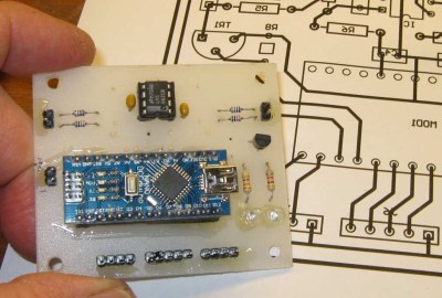 With FPGA code, IGBT wiring and power supply issues sorted, the next step was to add a supervisory micro-controller, using an Arduino Nano. Its functions included interfacing with a touch screen LCD as a user interface, communicating with the FPGA module, and controlling several relays to switch power to the motor power supply, the roughing pump, TMP cooling fan, and a solenoid for the vacuum vent. Spindle current is calculated by measuring voltage drop across shunt resistors on the low side of the IGBT. Motor speed is measured using one of the motor hall sensors, and a thermistor provides motor temperature sensing. [Mark]’s PCB fabrication technique seems a bit different too. Using an Excellon drill file, he drills holes in a piece of plastic using a laser cutter to create a bare board, and then solders copper tracks by hand.
His initial tests at atmospheric pressure (although not recommended unless you monitor pump temperature), resulted in 7300 rpm while consuming about 7 Amps before he had to shut it down. In further tests, after adding a roughing pump to the test setup, he was able to spin the TMP to 20,000 rpm while it consumed 0.6 A. Obviously, the pump is rated to operate at a higher voltage, possibly 48 V based on the values mentioned in the TMP controller manual. The project is still “work in progress” as [Mark] hopes to eventually drive the pump up to its specified 60,000 rpm operating speed. What is not clear is what he eventually intends to do with this piece of exotic machinery. All he mentions is that “he has recently taken an interest in high-vacuum systems and is interested in exploring the high-vacuum world of electron guns.”
Maybe [Mark] can compare notes with the Open Source Turbomolecular Pump Controller that we featured some time back. And if you’d like to be a little bit more adventurous and build you own TMP, we got you covered with this DIY Everyman’s Turbomolecular Pump.


Wow, seriously respect here
Nah, it sucks. Seriously though, a very impressive project!
Great project. The turbo’s from old semiconductor lines are almost always too expensive when they are sold with the controller. There are plenty for sale without a controller that are affordable, or at least about as much as a gaming PC.
By the way, when you are reading older material, the “backing (or roughing) pump” is likely to be called a forepump.
Anyone interested in chatting, feel free to join this discord chat server all about vacuum hacking https://discord.gg/EpjBG3wt82
Is that being run not in vacuum?
That’s one very quick way to destroy your TMP >.<
Most of the time, they will spin up to a reasonably high speed happily under atmospheric pressure. The controller monitors the motor absorbed power which will be higher at higher pressure due to blade drag, viscous effect etc.
Most OEM controllers hold the speed until either the absorbed power drops (i.e. improving vacuum conditions provided by the roughing/backing pumps or timeout due to high current and shut the pump down.
It is preferable to start TMP’s at the same time as backing pumps, especially with oil-based pumps as the spinning TMP helps reduce oil backstreaming into your high-vacuum area.
TMPs are not like ion-pumps or diffusion pumps which really don’t like being started at high pressure.
Easiest way to destroy a TMP is to either drop something into it when running or vent the system too quickly when a pump is or was running. The higher gas density leads to the rotor blades producing forces which can bend them upwards or downwards depending on the flow path and into contact with the stator stages which usually is catastrophic.
@anool, the PDF link is broken. It is currently a local filesystem file.
Thanks for spotting that. Fixed.
“All he mentions is that “he has recently taken an interest in high-vacuum systems and is interested in exploring the high-vacuum world of electron guns.””
Sputtering.
having personally witnessed the results of a failed turbomolecular pump, i would heartily encourage anyone building a controller for one to:
affix the pump to a large, immobile mass, like a granite plate so that it can’t be bumped
get some vibration sensors on it, and get your controller watching them both during start up, and operation
add some active braking, ideally powered by the energy in the motor itself, so you can quickly bring it to a controlled stop in the event of a power outage / rough pump failure before the vent side of the pump reaches atmospheric-ish pressures. (as mark notes, they can run at slow speeds in atmosphere, so you’ve just got to shed most of the energy before the pressure gets too high.)
How about you just slam a chunk of material into the rotating parts ruining them and the braking mechanism, requiring replacement of everything but bringing them to an instant stop? No wait, that method is patented :-D
Both rotary and (at least some) diaphragm pumps can hold vacuum well enough that in the event of loss of power, they’ll allow the turbo to slow at a sane rate.
It’s not a bad idea to test your roughing pump to ensure its seals are decent and it’ll hold rough vac when powered down, though!
with the vibration sensor, i should note that you’ll want to be able to sample fast enough to pick up things above human hearing. these things spin fast enough that “bad mechanical system noises” you’d be able to hear with other devices can occur up in the ultrasonic.
This is amazing that he got this far. Noting Moo’s comments are vital to the success of the project. It would be a shame/expensive (or worse) to damage it.
Thank you everyone for your comments. I have been lucky enough to acquire a complete and working turbo-pump system, so have a ready supply of 5e-6 Torr (if one can indeed have a ready supply of almost-nothing !). This system has guided the design of the TMP controller referenced. In terms of projects; home-made values (tubes), possibly a small SEM, investigation into mass spectrometry, sputtering, and if I can get far enough away, some ionization experiments :) Steve Hansen has an excellent free magazine, search for ‘the Bell Jar’. HNY, and stay well, Mark, New Zealand.
hi. does anyone knows how to build a driver for a circulation pump or get pcb from somewhere?
Type- Wilo, made in Europe. for more info google wilo circulation pump. I could not repair my pump cause it has 3 layers pcb and there was water inside. The pump is still in place with water system, i see 7 contacts from the motor, looks like 5 of them are used. 3 for phases and 1 pwm 1DC. Can anyone explain how to run this kind of motor? I can also paypal you for help, i cant replace pump cause its 6000 liter system and complicated.
Thank you.