The availability of inexpensive electronics modules has opened up a world of opportunity for more complex projects to be completed quickly. Rather than designing everything from scratch, ready-made motor modules, regulators, computer vision modules, and control modules all ready to be put to work after arriving at one’s doorstep. Sometimes, though, these inexpensive electronics aren’t all they’re cracked up to be, so [Jan] decided to produce them from scratch instead.
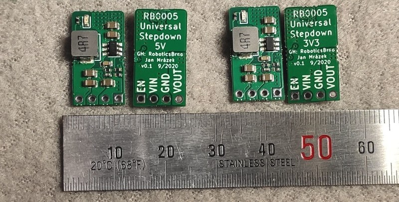
[Jan] is the creator of several robots, and frequently makes use of 3.3V and 5V step down modules, but was not happy with the consistency offered by the prefab modules. The solution to this was to build them from scratch in a way that makes producing a large amount nearly as easy as ordering them. The boards are based around the SY8105 chip, and are built in two batches for the robotics shop based on the two most commonly needed output voltages. With their design they get exactly what they need every time, without worrying about reliability from a random board shop overseas.
The robotics shop is called RoboticsBrno and they have made the schematics available for anyone that wants to build their own. That being said, the design does not make considerations for low noise since it isn’t required for their use case, but if you’d prefer something simple and reliable this will get the job done. It’s also important to understand the limitations of the parts in a build that are built by a third party, although power supplies are a pretty common area to make improvements on.


Where is the circuit diagram? I just see pretty pictures and nothing else.
https://github.com/RoboticsBrno/RB0005-UniversalStepDown
Good question… the schematic seems to be in some .sch format, not as easy to read as PDF or JPG.
But does it matter, just google SY8105 for the datasheet and you’ll see a schematic on the first page, the way it was intended by the designers of the IC.
You can add an LED to make it more complicated (and reduce efficiency by continuously shining a bright light in your face), but it isn’t rocket science.
All the sources are for KiCAD (the open-source EDA everyone can download), the GitHub repository with all the sources is linked on every page with the product (“See the project repository”, “Project sources”). Everything about the design is transparent, there is a Makefile for the fabrication files. With all the respect, what else can I, as an author, do to make the design “more open” so people don’t complain about being cryptic and secretive? I am really curious. Always, when any of my designs or research get published, people start ranting about this. So I am wondering what I could do better.
Yes, this project is not a rocket science. It is not supposed to be. It is a simple design, that fits our needs, e.g., for https://github.com/RoboticsBrno/RB3204-RBCX/ (ongoing project) used in our group to teach kids about robotics (https://robotickytabor.cz/gallery.html). But the design performs well and we guarantee it works – we desgined it, we measured it, we adjustit a we manufacture it, so we have the quality under control. Not like you get a different goods even from the same seller on Aliexpress. Unfortunatelly, for the kids we cannot afford buing 15$ modules from Pololu.
We put it on Tindie to make people easy to get it, if they have use for it. We often wonder “Ok, this is nice open project, but we have no time to study it and to manufacture it. Would it be possible just to get sample piece?” And I think makers putting stuff on Tindie is the way to go. It makes everyone life more pleasant. For me, as a consumer I can quickly get to working sample, the maker gets a little reward (don’t make illusion most of them make heavy money on it).
PS: If you look closely, the LED is powered over 47k – so it just barely shines, but does not make you blind. It is nice to be able to quicky see if the module is powered or not. It makes debugging so much easier! It draws 0.04 mA (0.00013 W). That’s such an efficiency killer! Especially when you power RC servos with it…
I am happy to hear you opinions!
Thanks for your work. Add a cuttable bridge to the led, so it can be easily and safely be disabled…
Hear. Hear! It always irritates me that those cheap chinese bucket converters are not layed out on a .1″ grid. Some pins are, but not in respect to others and certainly not for the whole board. Not fitting a breadboard is more common than not. Happy to see a nice single ended layout with enable pin.
Picture A Day?
Couch-critic-a-day?
Ok, Hackaday postponed my comment as it contined links, to I will try it again without links…
All the sources are for KiCAD (the open-source EDA everyone can download), the GitHub repository with all the sources is linked on every page with the product (“See the project repository”, “Project sources”). Everything about the design is transparent, there is a Makefile for the fabrication files. With all the respect, what else can I, as an author, do to make the design “more open” so people don’t complain about being cryptic and secretive? I am really curious. Always, when any of my designs or research get published, people start ranting about this. So I am wondering what I could do better.
Yes, this project is not a rocket science. It is not supposed to be. It is a simple design, that fits our needs, e.g., for RB3204-RBCX/ (ongoing project) used in our group to teach kids about robotics (robotickytabor.cz). But the design performs well and we guarantee it works – we desgined it, we measured it, we adjustit a we manufacture it, so we have the quality under control. Not like you get a different goods even from the same seller on Aliexpress. Unfortunatelly, for the kids we cannot afford buing 15$ modules from Pololu.
We put it on Tindie to make people easy to get it, if they have use for it. We often wonder “Ok, this is nice open project, but we have no time to study it and to manufacture it. Would it be possible just to get sample piece?” And I think makers putting stuff on Tindie is the way to go. It makes everyone life more pleasant. For me, as a consumer I can quickly get to working sample, the maker gets a little reward (don’t make illusion most of them make heavy money on it).
PS: If you look closely, the LED is powered over 47k – so it just barely shines, but does not make you blind. It is nice to be able to quicky see if the module is powered or not. It makes debugging so much easier! It draws 0.04 mA (0.00013 W). That’s such an efficiency killer! Especially when you power RC servos with it…
I am happy to hear you opinions!
Seriously, a PDF of the schematic should be the first thing you generate when you publish a circuit. Most prospective users / clients etc want to quickly see what the circuit looks like, not open a project or anything like that, even if they have the CAD programs on hand.
I’ve seen designers actively refuse to generate PDF files, saying that the design files are all you need. It may be what is needed to modify it, or to reproduce it, but we all like learning, and 90% of the time people just want to see the circuit or schematic on their phone while out etc.
My 2c.
I do kinda have to echo this sentiment. There have been several reasonable interesting project around the Internet, but they’ve all required installing this or that schematic-viewer/-designer to view and I’ve just ended up groaning and moving on.
All modern OSes and browsers have PDF- and image-viewing capabilities built-in, so it’s just a lot more convenient to have the schematics available in one of those formats.
Anyways, it’s a matter of taste in the end, so can’t really fault the designer for having different tastes and preferences, either.
Thank your for constructive feedback. Ok, I will think about it with my next project and I will genrate PDF schematics. One more question; on most of my projects I just leave a link to Cadlab.io. Would that be OK for you (I missed it in this project).
Just to give you the other point of view; once you have a complicated schematics, reading PDF or image is annoing as you cannot easily go up and down in the sheet hiearchy, you cannot click net labels or highlight them. Thus, I feel no need for PDFs nor images.
Replying on the netlist posting of Jan Mrazek.
Some schematics avoid actual wires, just giving every pin used a label. I never can follow those schematics as you never know what pins are used. But a pdf gives a quick look and if you make revisions of a board, you can have them open next to your current project and see differences between versions.
To be serious, are you telling me that a half page schematic would use heirachy approach?
Think of it as an executive summary. No one is going to bother wasting time going down to the nifty detail if they are not convinced that your project is up to snuff.
tekkieneet: I am not talking about this project; that’s why my senteces started with “once you have a complicated schematics…”
Pdf is also straight ready for the printer, surely nobody here ever solders up a custom PCB without having a printed diagram (both of schematic and layout, both sides) at their side.
Jackie: I have never, ever printed schematics or board layout. I always use monitor – it is interactive; you can easily highlight your components, show/hide them. Much more pleasant to work.
Also, when you have sources instead of PDF you can use: https://github.com/openscopeproject/InteractiveHtmlBom
Thank you for non blinding leds. I replace the led resistors on a lot of devices because they hurt my eyes.
step-down from 48v so it can be used in PoE apps :)
Don’t worry about whiners. They just gotta whine.
Thanks for Making! And thanks for making available your knowledge.
I was looking at this and comparing it to https://hackaday.com/2021/01/12/smart-power-delivery-for-long-led-strips/ thinking that they look very similar…. then I looked at the creators :-)
I’m amazed that there aren’t better quality items more widely available so well done [Jan].
I had a similar problem. I ended up designing a voltage regulation (charge pump in my case) with an added lithium ion charge circuit into a small project because buying a few charger circuits was proving wildly inconsistent. Some of the parts wouldn’t properly shift chargIng amperage to the ~30mA range I needed.
Thanks for sharing the design!
I’ve really only got two comments, though I do like what I see in general.
1. Why no mouting holes? Especially on a robot, it looks like it would be floating free in space unless you put headers on it, which might be your answer.
2. Would it make more sense to put the in/out on seperate ends, so they’re less likely to get mixed up? And ideally with non-symetrical headers so you can’t plug them in backwards? Or if you do, so they don’t matter? Just a thought.
3. How much power can they handle? It would be nice if that basic info was on the silkscreen.
Darn, one too many comments! Really questions, but I like what I see. Thanks for doing and sharing!
Hi, thank you for your questions.
1, 2) This more-less designed to be mounted to a PCB (perpendicular to the main board). It also has the same pin ordering as LM7805 which is featured in some of our older desings. Thus we aimed for small footprint.
3) Does https://roboticsbrno.github.io/RB0005-UniversalStepDown/eval5v_v2/ answer your questions? The answer about power capabilities always a more complicated, thus not suitable on silkcreen. I think it is more important to put at least GitHub organization name on the silkreen, so people can track the design and learn more.
Thanks, that answers alot of my questions. I still think you might want to put some limits on the silkscreen, even just 18v, 3a would be nice. But I can see why not. Nice work!
Bit of a newbie question, but what are the dimples (for lack of the proper term) in the large traces for? (Like at the top-right of the board). I’ve seen this on a few PCBs before, they look like vias but why are there so many?
These are vias – a copper plated hole that connects two (or more) layers on the PCB. There a number of them to be able to carry more current and also heat. Currently, I think there are probably more of them than it is necessary in the design.
These are via, mostly used for thermal and high power routing between sides.
Adding to the previous answers: The specific technique of putting multiple vias close to each other, to join traces or pours in different layers, is called ‘via stitching’.
By using multiple vias you essentially lower the impedance in the path between the traces/pours. Thereto it improves thermal transfer between the layers, which is commonly used by IC’s with thermal pads.
Thank you! Knowing that it’s called ‘via stitching’ helps a lot with searching for more info.
That’s interesting, I always assumed one via was enough.
What baffles me a bit is why the SY8105? It’s difficult to find a datasheet for it. According to octoparts basically no-one stocks it. Ok, LCSC has it. If you’re going for something more reliable than the cheap aliexpress converters, why not use a widely available chip from a reputable manufacturer? (Which then also has a much better datasheet…)
Difficult to find a datasheet for it? No one stocks it? I just double clicked it in your comment, right clicked and then clicked Search Google for “SY8105”. Literally the first 5 results were datasheets, and then there was a shop offering tens of thousands for sale (yes probably only in large quantities, but that’s why modules like this exist). I gave up looking after that as I’m assuming you only went to your local corner shop and asked for it.
Interesting, DDG has trouble finding the datasheets, you’re correct that googlag serves them right up, sigh. Corner shop? What’s that???
Yes, you can order a pile of these chips from china, but then, what’s the difference vs. ordering a bunch of modules from china?
These modules are made by an individual maker, not a factory in China, and they’re also available in quantities with fewer than four digits.
A corner shop is a small, local, convenience shop. The independent ones are often tightly packed with an eclectic mix of goods for sale, you usually pay a small premium for the convenience, and freshness and quality can suffer in some. A corner shop should not be conflated with Cornershop though, the band from the 90s that released the single “Brimful of Asha”.
I thought so too but recently I looked into making such a step-down converter myself and found out only pure chinesium can be shaped in human-solderable parts these days. Other reputable manufacturers of such chips chose smaller and smaller packages and the older parts they provide do not have the same efficiency and/or current output as the Chinese counterparts. A SOT23-6 is definitely easier to solder and simpler to use than a QFN or BGA part with much more pins at a minimum.
Did you see the TPS565201? Looks pretty equiv, but I haven’t delved into the details.