Stepping Down Voltage With Reliability

The availability of inexpensive electronics modules has opened up a world of opportunity for more complex projects to be completed quickly. Rather than designing everything from scratch, ready-made motor modules, regulators, computer vision modules, and control modules all ready to be put to work after arriving at one’s doorstep. Sometimes, though, these inexpensive electronics aren’t all they’re cracked up to be, so [Jan] decided to produce them from scratch instead.

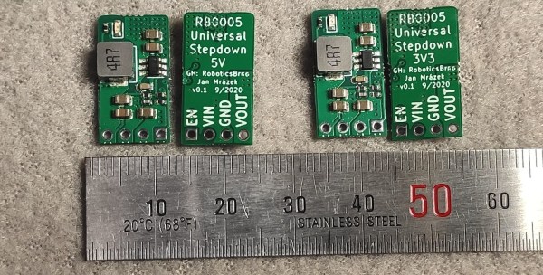
[Jan] is the creator of several robots, and frequently makes use of 3.3V and 5V step down modules, but was not happy with the consistency offered by the prefab modules. The solution to this was to build them from scratch in a way that makes producing a large amount nearly as easy as ordering them. The boards are based around the SY8105 chip, and are built in two batches for the robotics shop based on the two most commonly needed output voltages. With their design they get exactly what they need every time, without worrying about reliability from a random board shop overseas.

The robotics shop is called RoboticsBrno and they have made the schematics available for anyone that wants to build their own. That being said, the design does not make considerations for low noise since it isn’t required for their use case, but if you’d prefer something simple and reliable this will get the job done. It’s also important to understand the limitations of the parts in a build that are built by a third party, although power supplies are a pretty common area to make improvements on.

Circuit Challenge: Two Transistor 3.3V Regulator

[Kevin Darrah] wanted to make a simple 3.3V regulator without using an integrated circuit. He wound up using two common NPN transistors and 4 1K resistors. The circuit isn’t going to beat out a cheap linear regulator IC, but for the low component count, it is actually pretty good.

In all fairness, though, [Kevin] may have two transistors, but he’s only using one of them as a proper transistor. That one is a conventional pass regulator like you might find in any regulator circuit. The other transistor only has two connections. The design reverse biases the base-emitter junction which results in a roughly 8V breakdown voltage. Essentially, this transistor is being used as a poor-quality Zener diode.

Continue reading “Circuit Challenge: Two Transistor 3.3V Regulator”

Taking It To Another Level: Making 3.3V Speak With 5V

If your introduction to digital electronics came more years ago than you’d care to mention, the chances are you did so with 5V TTL logic. Above 2V but usually pretty close to 5V is a logic 1, below 0.8V is a logic 0. If you were a keen reader of electronic text books you might have read about different voltage levels tolerated by 4000 series CMOS gates, but the chances are even with them you’d have still used the familiar 5 volts.

This happy state of never encountering anything but 5V logic as a hobbyist has not persisted. In recent decades the demands of higher speed and lower power have given us successive families of lower voltage devices, and we will now commonly also encounter 3.3V or even sometimes lower voltage devices. When these different families need to coexist as for example when interfacing to the current crop of microcontroller boards, care has to be taken to avoid damage to your silicon. Some means of managing the transition between voltages is required, so we’re going to take a look at the world of level shifters, the circuits we use when interfacing these different voltage logic families.

Continue reading “Taking It To Another Level: Making 3.3V Speak With 5V”

Ask Hackaday: Is The ESP8266 5V Tolerant?

The ESP8266 is the reigning WiFi wonderchip, quickly securing its reputation as the go-to platform for an entire ecosystem of wireless devices. There’s nothing that beats the ESP8266 on a capability vs. price comparison, and this tiny chip is even finding its way into commercial products. It’s also a fantastic device for the hardware tinkerer, leading to thousands of homebrew projects revolving around this tiny magical device.

In every technical document, summary, and description of the ESP8266, the ESP8266 is said to be a 3.3V part. While we’re well into the age of 3.3V logic, there are still an incredible number of boards and hardware that still operate using 5V logic. Over on the Hackaday.io stack, [Radomir] is questioning this basic assumption. He’s wondering if the ESP8266 is 5V tolerant after all. If it is, great. We don’t need level converters, and interfacing the ESP to USB TTL serial adapters becomes much easier. Yes, you’ll still need to use a regulator if the rest of your project is running at 5V, but if the pins are 5V tolerant, interfacing the ESP8266 with a variety of hardware becomes very easy.

[Radomir]’s evidence for the possibility of 5V tolerant inputs comes from a slight difference in the official datasheet from Espressif, and the datasheet translated by the community before Espressif realized how many of these chips they were going to sell.

The best evidence of 5V tolerant pins might come from real-world experience — if you can drive a pin with 5V for months on end without it failing, there might be something to this claim. It’s not definitive, though; just because a device will work with 5V input pins for a few months doesn’t mean it won’t fail in the future. So far a few people have spoken up and presented ESPs directly connected to the 5V pin of an Arduino that still work after months of service. If this is evidence of 5V tolerant design or simply luck is another matter entirely.

While the official datasheet from Espressif lists a maximum VIH of 3.3V, maximum specs rarely are true maximums — you can always push a part harder without things flying apart at the seams. Unfortunately, unless we hear something from the engineers at Espressif, we won’t know if the ESP8266 was designed to be 5V tolerant, if it can handle 5V signals reliably, or if 5V signals are a really good way to kill a chip eventually.

Lucky for us — and this brings us to the entire point of an Ask Hackaday column — a few Espressif engineers read Hackaday. They’re welcome to pseudonymously chime in below along with the rest of the peanut gallery. Failing that, the ESP8266 has been decapped; are there any die inspection wizards who can back up a claim of 5V tolerance for the GPIO? We’d also be interested in hearing any ideas for stress testing pin tolerance.

Transmitting MIDI Signals With XBEE

What do you do when you want to rock out on your keytar without the constraints of cables and wires? You make your own wireless keytar of course! In order to get the job done, [kr1st0f] built a logic translator circuit. This allows him to transmit MIDI signals directly from a MIDI keyboard to a remote system using XBEE.

[kr1st0f] started with a MIDI keyboard that had the old style MIDI interface with a 5 pin DIN connector. Many new keyboards only have a USB interface, and that would have complicated things. The main circuit uses an optoisolator and a logic converter to get the job done. The MIDI signals are converted from the standard 5V logic to 3.3V in order to work with the XBEE.

The XBEE itself also needed to be configured in order for this circuit to work properly. MIDI signals operate at a rate of 31,250 bits per second. The XBEE, on the other hand, works by default at 9,600 bps. [kr1st0f] first had to reconfigure the XBEE to run at the MIDI bit rate. He did this by connecting to the XBEE over a Serial interface and using a series of AT commands. He also had to configure proper ID numbers into the XBEE modules. When all is said and done, his new transmitter circuit can transmit the MIDI signals wirelessly to a receiver circuit which is hooked up to a computer.