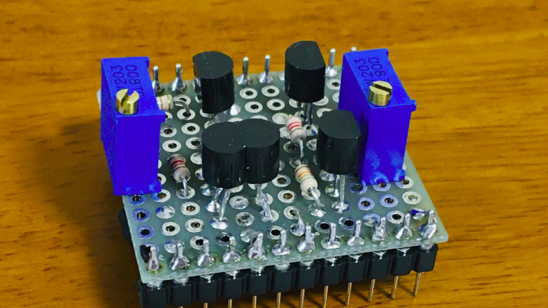
If we had to pick one part to crown as the universal component in the world of analogue electronics, it would have to be the operational amplifier. The humble op-amp can be configured into so many circuit building blocks that it has become an indispensable tool for designers. It’s tempting to treat an op-amp as a triangular black box in a circuit diagram, but understanding its operation gives an insight into analogue electronics that’s worth having. [Mitsuru Yamada]’s homemade op-amp using discrete components is thus a project of interest, implementing as it does a complete simple op-amp with five transistors.
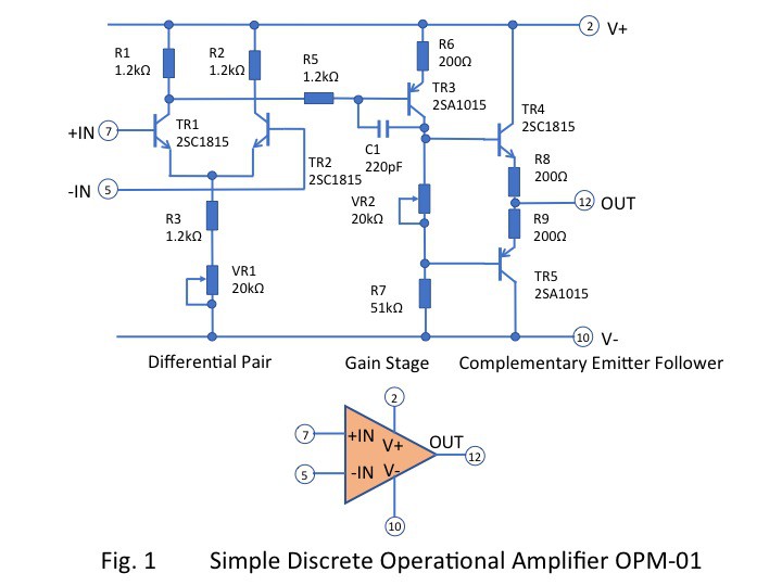 Looking at the circuit diagram it follows the classic op-amp with a long-tailed pair of NPN transistors driving a PNP gain stage and finally a complimentary emitter follower as an output buffer. It incorporates the feedback capacitor that would have been an external component on early op-amp chips, and it has a couple of variable resistors to adjust the bias. Keen eyed readers will notice its flaws such as inevitably mismatched transistors and the lack of a current mirror in the long-tailed pair, but using those to find fault in a circuit built for learning is beside the point. He demonstrated it in use, and even goes as far as to show it running an audio power amplifier driving a small speaker.
For the dedicated student of op-amps, may we suggest further reading as we examine the first integrated circuit op-amp?


“…and finally a complimentary emitter follower”.
Can I have one too if they are free?
I had to pay for mine, but they do say nice things about you all day.
Cool article. I like hearing about back to basics minimalism.
I think you may have misunderstood.
This is an emitter that tells you how good you look today.
We had to do that in school, and though we did use a matched pair for the gain stage and a current mirror on top with a pot for the offset it wasn’t easy for a total newbie.
But there’s only one transistor for the gain stage here.
The gain stage is a single transistor class A. The differential input is where matching is necessary.
We matched transistors . tested gain for each and also a simple circuit. Then build similar op amp
Or as what we used to call it, an amplifier. ;)
We also used to call it complementary symmetry.
The difference between an op-amp on a silicon die and a discrete amplifier is thermal stability. 20K ohm is probably very high for the adjustable bias resistor. I’d recommend 2 silicon diodes in series with VR2 with VR2->diode1-> diode2 between the bases of the output transistors. At low power there shouldn’t be any thermal runaway but the base to emitter voltage changes with temperature which means that the common current in the output transistors will probably change over temperature range. The diodes will compensate for this. Probably bias with about .3 V drop across the 2 emitter resistors to put it into class AB1. Depending on the supply voltages, VR2 is probably in the 1K to 2.5K ohm range.
Thank you for the advice on the bias circuit with diodes. I put VR2 on to experience the crossover distortion that can be observed when it is set to 0 ohm. The potentiometer I have on hand is 20 k ohms, so I’m using it for both VR1 and VR2. I did not optimize the values.
Might I suggest connecting the collector of TR2 to the emitter of TR3 and omitting R2.
Understanding the difference in operation would be a good learning tool.
Why so bitter, bro?
I don’t know if you live in EU or USA but in EU in case of war there may be no supplies of electronic parts. If you can improvise an op-amp or 555 from parts found in old TV or electric scooter then you could make a radio, fix a computer PSU or do other things for war effort. This is why such knowledge must be taught and preserved.
In case of a war, I have much higher priority things than making an opamp. i.e. things like food, fuel, water, basic medicine etc.
Having been a soldier (infantry), the most scarce resource is skilled personnel. Having any high-tech skill (medicine, machining, electronics, programming maybe) increases your value to a group. Militia members know this. The last person I’m asking to dig a ditch in a war zone is the one guy that can keep our comms up.
In case of a shortage of electronics parts, matched transistors will be much harder to come buy than the billions of opamps still lying in warehouses. matched transistors are definitely niche parts, and the EU, contrary to your assertion, has some large semiconductor fabs – especially for low-tech ICs like Opamps. For example, look up Nexperia, NXP. In fact, building an opamp that’s better than even a good discrete implementation takes less 1980’s technology – and even the former Eastern Germand Republic had fabs for these. These fabs haven’t all gone away – it’s just not profitable to operate them to build µ741.
Opamps existed long before ICs.
So they are existed in tube form.
Then done with transistors.
I have a module, I think from Analog Devices, which is an op-amp about the size of a small matchbox. I think a hybrid, between discrete transistors and ICs.
About 1973 Radio Electronics had an article, I think from SWTP, for building an opamp. They wanted something better than the 709 or maybe 741, for audio ourposes.
And other than specs, each one of these opamps could be presented by the same symbol, and the external circuitry would be the same.
I wonder if opamp IC symbols would have pins for filament voltage. :P
You just need to know how to search for them. Discrete Semiconductor Products/Transistors – Bipolar (BJT) – Arrays
There are options specifically for matching pairs. Array is built on same die, so that solves the matching issue and still reasonably cheap.
Digikey sells matched pair transistor array.
DMMT5551-7-F $0.43 at QTY 1 – TRANS 2NPN 160V 0.2A SOT26
DMMT3904W-7-F $0.37 at QTY 1 TRANS 2NPN 40V 0.2A SOT363
Considering those are SMDs and that through-hole matched pairs come in DIPs, it kinda’ misses part of the point of the “discrete” aspect of this project.
Simply pointing out that there are much better and more economic way of getting matched transistors.
Your not being able to solder modern parts has nothing to do with a part being discrete or not.
I know that. I used earlier versions of monolithic matched transistors over 40 years ago. RCA (when it still “was” and had a semi arm), was a pioneer is that, especially for RF use (like RF gain amps). But you missed my point: today’s op amps can’t be beat since they are so cheap and perform better than anything can be cobbled together because ALL of it is monolithic (better temperature tracking, matching, etc.), unless you “really” want to make something discreet or even a tube op amp. Yeah, you might get a kick out of that and some esoteric bragging rights, but give me a great off-the-shelf IC op amp any day.
And you overlooked my PSPICE point, which has also evolved a lot and runs soooo much faster on today’s PCs, tablets, etc. With PSPICE, you can “cobble” a design and verify it quickly using tools that emulate oscilloscopes, signal generators, and other high-end analog gear that’s way too expensive for hobby use. And the model fidelity have greatly improved over the years. Why not use the best tool for the job?
Spice is not interactive and does not behave like real parts. You only understand it properly, when the circuit was built by hand and works as well.
Simulation is great for digital logic, or when you try to figure out some details, but have a good understanding. For gaining a basic understanding, real world practice is superior to analog simulation.
Some things are hard to model too, for example transformers, and you need to know a lot to model them before you can start “experimenting”.
A lot of this is not ideal from a learning perspective.
Having a working kit with well explained examples, and expected outputs is a lot better, than figuring it out all theoretically, then discovering it doesn’t work like this in real, and wondering why.
Most people who’d build this aren’t going to do any testing. It’s another project to them.
I suppose there are some people who think that building this will give them some insight.
There are still people today who dismiss “complication”, so they avoid ICs (too many parts) rather than treat it more as a function block. They haven’t made the steps to know that some of the “complication” of even simple ICs is because it costs nothing, or some transistors are there because they replace large value resistors or other components that are hard or costly to put in an IC.
So actually building an opamp (or 555) will help such people get a grasp on ICs (or maybe they think it will)
Not overlooking it… I am using the egeric term. PSPICE is a specific version of Spice.
I did mention that you can measure things that can’t be done easily in real life. Not everyone has a spectrum analyzer for measuring THD or transfer charastic (phase/gain over frequency).
Personally I would stick to a spice derviative not junk like falstad. They are used for serious engineering work, so there are some good models around. I have spent close to a month on LTSpice when I was working on a power supply project. The simulator predicted the problem I saw in the lab and I managed to try out easily half a dozen of alternatives in an afternoon instead of wasting my time in the lab.
Outcome: I finished a design that works on first rev and pass compliance test in 6 months while another guy that wasted those 6 months in the lab tweaking his design with and no deliverables.
I beat my head for a week trying to fix an avionics tester, because we literally couldn’t get a particular matched pair anymore. I took all the unmatched transistors in the stockroom, traced each one by hand, installed the closest pair, and saved a $60K tester. And no, you can’t get aviation/military grade parts from just anywhere (if you want to stay out of jail).
Can’t agree more on spice as you get to tweak the parameters *and* test for a lot of things that you can’t test or don’t have equipment to test e.g THD, performance over temperature, component variations
Falstad would be better, Spice is not interactive. Most simulators leave a lot to be desired, even today.
I wouldn’t do anything critical with the Falstad simulator, since their diode and transistor models are pretty simple and don’t replicate a lot of real world behavior.
I once tried to model a guitar fuzz pedal (a kind of diode clipper) with the simulator and it looked like it wouldn’t even work.
the simple transistor model is consistent with the educational purpose of Falstad’s circuitjs. Funnily the diode & LED models are more elaborate.
But right now I have a lot of trouble with simulating a bipolar bucket brigade with circuitjs…
The interactivity is however critical and we hope the models will get better. circuitjs seems to be under active development so there is hope :-)
Spice is a known quantity and used in the industry. People design chips and serious stuff using it. It delivery result not pretty animations for noobs.
Then again, any circuit simulator will have simplifications and idealizations that will trip you. For example, what about EMI? Or what about the impedance (and microphonics) of a wirewound resistor instead of a carbon film resistor?
It’s like they say, you can’t learn to swim from a book. At some point you have to dive in.
It’s a “simulation”, right? But you can “tune” the granularity (i.e. simulation resolution) as a tradeoff versus speed of execution. But as I said, its to much better than it used to be.
And seriously, who would use a wirewound resistor in any op amp circuit? And how would a reputably made wirewound resistor be microphonic? What phenomenon is at work there? I did a quick search and the only references I saw were for tube amp and not for wirewound resistors, but for (poorly made or old) carbon composition resistors (made “similar” to the old carbon particle phone microphones of the early 70’s and earlier). I’ve (literally) heard ceramic capacitors “sing” in old tube radios and TVs because they are piezoelectric transducers too, but modern manufacturing has mostly eliminated that, plus there are much better alternatives to using ceramic caps in audio circuits for anything more than RF bypassing.
Sure, you have to get “wet” but don’t dive in the deep end before you know what you’re doing, right?
Your simulation is only as good as your model. Simulators handles the tough part of doing the maths. The physic is there and it is a matter of what level of details you want in a model vs computational needed.
If *you * use simplifications and idealizations, then the fault is on you not the simulators.
This guy here has a page with a lot of discrete op amps – of course, all of them have way more than 5 transistors,
but some interesting ones (use google translate as this page is in Polish)
https://forum.audiofanatyk.pl/profile/8-blondie/content/page/6/?type=forums_topic_post
In truth, understanding op-amps begins with the math, like here https://en.wikipedia.org/wiki/Negative-feedback_amplifier#History. Not with a discrete circuit, which can be taken from any op-amp IC diagram.
That isn’t a complaint (except about HaD headline-ism) and this is a very worthwhile project, specifically considering you can probe circuit nodes normally unreachable in an IC.
A fantastic project I would like to see is a discrete Delta-Sigma ADC.
I wouldn’t trust PSPICE as my only learning tool. Should you learn how to use it (or some other circuit simulator like LTSPICE)? Yes. But it for concepts like these, a physical model tends to be very valuable. Let’s just say that I feel sorry for the electrical engineering students who are online and can only simulate their labs. It work, but you loose out on some of peculiarities that you need to account for when dealing with real hardware.
i’ve seen a ton of these sorts of schematics over the years but this is the first time (in part because it’s so braindead^H^H^Hsimplified) that the differential pair on the input has made sense to me. i think i finally get it! TR2 pulls its lower end up to V- minus a bias voltage, and then TR1 activates based on the difference between V+ and V- with the two bias voltages canceling eachother out neatly.
so..thank you!
Physically bumbling about with the building blocks of basic IC’s help people who don’t have that great grasp on theoretical learning understand it.
I know because I’m part of the “hands-on approach” when it comes to learning even though I can handle theoretical to help augment the materialistic manhandling.
And things like Pspice needs its own lecture on itself, Falstad circuit simulator is a better bet for a rookie.
All true.
You might have to read more of the author’s had.io output to see that he knows about ic amps and simulation. I don’t think he said you need to do the same project the same way for the same reasons.
In an admittedly brief search, I didn’t find anything about PSPICE simulating junction thermal response to touching a TO-92.
I suspect there are accomplished painters who occasionally use their fingers.
Certainly looks cooler than an IC. Is this sort if like building a bookcase instead if buying one from a box store? Just made one myself, wouldn’t think of buying one, from scrap no less. Learned some stuff, not seen on youtube, spice for building other stuff. Made that solarbotics Herbie light seeker, harvested most of the parts from e-waste, learned some stuff from that as well, which the how-to in the book didn’t mention, the book would be spice in this case.
This is more like growing the tree to build the bookcase rather than buying the wood at the lumber yard I think.
Built my first one using 2N2926 green and yellow transistors for an analogue computer. Temperature drift was an issue due to high gain, up to 100,000 then as I recall.
R1 is there to balance the current through to the input pair and is usually larger than R2. R5 is only needed for stability and is often omitted. C1 seems quite high so I guess that was an issue. Base resistors on TR4 and 5 might work better.
Thank you for the advice. I have set C1 to a fairly large value to avoid parasitic oscillation, and I haven’t done a rigorous evaluation of C1.
I wonder what the specs are for the opamp. The only spec I saw in the link was if the phase capacitor is removed gain-bandwidth product increases to 4 MHz which is like 10x better than an antique 741 opamp. Then again looking at the output stage I bet it can’t output rail to rail. I wonder if this amp can beat the slew rate of an ancient 741 which is less than 1 volt per uS (modern opamps are like thousands of V per uS slew rate). Also remember that some of the oldest opamps were absolute power pigs like each 741 draws about a quarter watt just sitting there and I wonder if this design can beat a 741?
Remember the 741 was NEVER a very good amp, it was just very easy to buy one chip rather than build an entire PCB sized amp, so I bet someone can can out perform a 741 pretty easily… the question is … how easily? I think its gonna take more than 5 transistors to crush a 741. What if you used some FETs on the input and some modern VHF transistors to get better gain/bw product and some beefy FETs on the output stage to get massive slew rates… Maybe end up building a high power oscillator accidentally LOL who knows..
The 741 was a vast improvement over what came before. In a box of junk I once got some 702s or maybe 706s, and the internal circuit was really different. I may have thrown those out when I realized they offered nothing.
“For a long time” you could get some better opamps, but you’d pay. This one had way better speed, that one way better input imoedance.
As Irecal, around the same time, 1’977 or 78, RCA and TI both came out with better opamps about the same time. Same end, different processes. But cheap.
uA741 was nearly a miracle at the time. I recall a 1-day build (including buying parts and making PCBs!) with a professor of mine in Seattle. IIRC two 741’s as PSU regulators from a voltage doubler to get +15 -15. Two 741’s in the seismometer (Klystron magnets from a surplus microwave amplifier and a coil we made that day and some wood) amplifier, each with gain of 1000 and active filter in the feedback. And one 741 in the pen motor – another coil and Klystron magnet – with a complementary pair of TIP29/TIP30?
Incredibly good results and so few parts! But yes, for low frequency that involves integration it was pretty bad. Shortly after this the LM308 became widely available and was so much better there as almost no comparison. LM308 for gain and noise and offset became the goto unit and I think LM358 for speed. When I look at modern low cost op-amp specs they are so close to ideal that it is hard to choose. I have not idea if there is a modern jellybean choice like the 741.
It is funny that for noise, power, and dynamic range the early op-amps were + and – 350 volts or more, then around 60V in some analog computers, then 35, then 741 era and +-18V. Now they are on a par with the digital chip voltages. +-3V or 1.8V
The performance of this op amp is far below that of the type 741 in terms of low open loop gain and offset characteristics.
I have used the 741 and 308 in the past.
hmmmm I should try to make one with Ge transistors ;-)