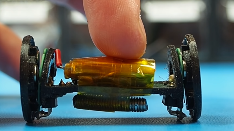
[Carl Bugeja] has been working on his PCB motors for more than three years now, and it doesn’t seem like he is close to running out of ideas for the project. His latest creation is a tiny Bluetooth-controlled robot built around two of these motors.
One of the main challenges of these axial flux PCB motors is their low torque output, so [Carl] had to make the robot as light as possible. The main board contains a microcontroller module with integrated Bluetooth, an IMU, regulator, and two motor drivers. The motor stator boards are soldered to the main board using 90° header pins. The frame for the body and the rotors for the motors are 3D printed. A set of four neodymium magnets and a bearing is press-fit into each rotor. The motor shafts are off-the-shelf PCB pins with one end soldered to the stator board. Power comes from a small single-cell lipo battery attached to the main board.
The robot moves, but with a jerking motion, and keeps making unintended turns. The primary cause of this seems to be the wobbly rotors, which mean that the output torque fluctuates throughout the rotation of the motor. Since there are only two points of contact to the ground, only the weight of the board and battery is preventing the central part from rotating with the motors. This doesn’t look like it’s quite enough, so [Carl] wants to experiment with using the IMU to smooth out the motion. For the next version, he’s also working on a new shaft mount, a metal rotor, and a more efficient motor design.
We look forward to seeing this in action, and also what other application [Carl] can come up with. He has already experimented with turning it into a stepper motor, a linear motor, and a tiny jigsaw motor.


Hmm, nice one, pertinent video, well done,
Thanks for posting :-)
Having 6 coils, in 3 phase, I don’t see any way to get a smoother functioning rotation at low speed outside of the circuit being able to overlap phases which is going to reduce efficiency and increase power drain and require a much more suf. circuit. Motors in this realm of design were intended to spin faster. More poles, smoother operation but at lower rpm. Seems to me size is everything with this. Making the magnets smaller, along with the coils and adding more poles will smooth out that jerky motion as the pulses would result in a much closer, shorter moment of arc motion. I’m thinking this would result in slightly better torque as well. Reshaping the coils to a narrower dimension, the pie slice shape is good and magnets of the same or very narrow rectangles would help. It just needs more poles to get it operating smoother and even that will be a small gain as the rpm will still be very low but that seems to be the object. Problem is, getting the traces right, perhaps a multi layer board would help, that way the coils could be overlapped, the idea of using a flexible PCB and laminating them? Yes I think getting the coil count up and staggering them along with more magnets is a good idea, the only thing I could see with that would be getting induced current in coils overlapping and causing issues with the control circuitry, then having to use diodes to blank out the un wanted currents.
I just noticed the Y symbol on the board, this must be the connection for the coils? WYE is a higher speed configuration generally. Perhaps Delta would be a better option as it works better at lower speeds and may assist in torque along with smoothing the motion since some of the current would go around through the other 2 coils. This may add current draw also. That is what I saw when working on large scale motors and generators. Delta produced higher torque and slightly lower speeds.
You have it swapped.
Delta = full speed, 1/2 torque.
Wye = 1/2 speed, full torque.
Given the same voltage/current input.
The way I remember the difference:
Delta has the coils in parallel, so the back EMF voltage is less, allowing higher speed.
Wye has the coils in series, so the torque is more coils (turns) per Amp.
Sorry to disappoint but the only difference between Delta and Wye is the voltage tolerance of the winding.
This is patently false.
I’m sorry to be that person, but, with regards to the title of this article…
http://www.angryflower.com/itsits.gif
Thanks for that. People who write in English for a living should be able to write passable English.
Glad it’s not only me. :)
> Thanks for that.
Correction: Thank you for that. Without a subject your sentence is a fragment.
People who criticize others for their English should be able to write passable English.