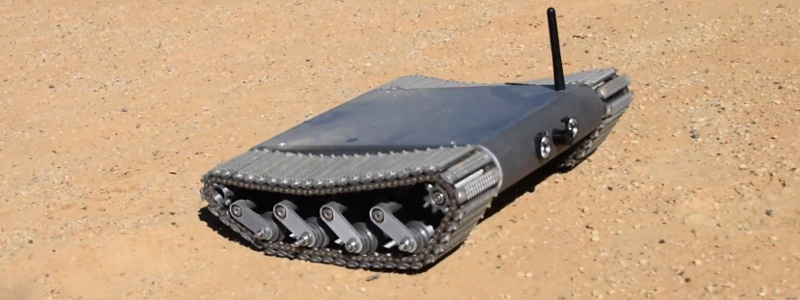
Inspired by battle-hardened military robots, [Engineering Juice] wanted to build his own remote controlled rover that could deliver live video from the front lines. But rather than use an off-the-shelf tracked robot chassis, he decided to design and 3D print the whole thing from scratch. While the final product might not be bullet proof, it certainly doesn’t seem to have any trouble traveling through sand and other rough terrain.
Certainly the most impressive aspect of this project is the roller chain track and suspension system, which consists of more than 200 individual printed parts, fasteners, bearings, and linkages. Initially, [Engineering Juice] came up with a less complex suspension system for the robot, but unfortunately it had a tendency to bind up during testing. However the new and improved design, which uses four articulated wheels on each side, provides an impressive balance between speed and off-road capability.
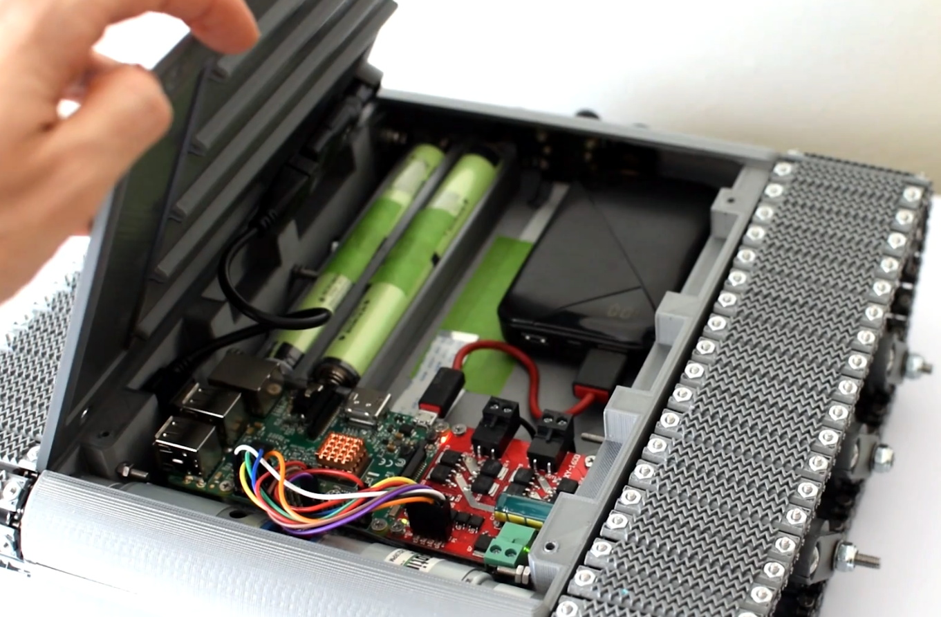 Internally there’s a Raspberry Pi 4 paired with an L298 dual H-bridge controller board to drive the heavy duty gear motors. While the Pi is running off of a standard USB power bank, the drive motors are supplied by a custom 18650 battery pack utilizing a 3D printed frame to protect and secure the cells. A commercial night vision camera solution that connects to the Pi’s CSI header is mounted in the front, with live video being broadcast back to the operator over WiFi.
To actually control the bot, [Engineering Juice] has come up with a Node-RED GUI that’s well suited to a smartphone’s touch screen. Of course with all the power and flexibility of the Raspberry Pi, you could come up with whatever sort of control scheme you wanted. Or perhaps even go all in and make it autonomous. It looks like there’s still plenty of space inside the robot for additional hardware and sensors, so we’re interested to see where things go from here.
Got a rover project in mind that doesn’t need the all-terrain capability offered by tracks? A couple of used “hoverboards” can easily be commandeered to create a surprisingly powerful wheeled platform to use as a base.


that picture is not showing a Raspberry Pi 4 though
It appears to be a Raspberry Pi 3. https://socialcompare.com/en/review/raspberry-pi-3
Yes, this was recently upgraded to a 4.
how cleaning camera lens?
what happened if device flip?
on desert are HOT, why not instaling radiator outside?
Is a BREAKABLE antenna sticking up “tactical’? Wouldn’t an internal one allow it to go more places?
Impressive project, but while the tracks give it some sort of military flavor, the actual use case for them involves a structure so heavy (or ground so soft) that the vehicle will bog down without them. They introduce a substantial point of failure: jammed bogies and drive wheels that may even lead to losing the track – a few bits of gravel might stop this machine cold. With this vehicle (and a lot of others, including Mars rovers) the light structure favors the debris-shedding ability of wheels – even flotation wheels – whenever practical.
The design to me looks very solid on the durability front, maybe it will need tweaking down the line as problems are found, but its miles better than most small tracked platforms as the suspension travel looks significant enough to deal with debris in the trackwork for the few rotations it will take to get thrown out – it would have to be pretty serious sized stuff to get pulled through and cause it to loose a track…
Tracks also generally deal with rough terrain far better than wheels – there is always a large contact patch providing great grip.
And as you point out being tracked makes it vastly better on very soft surfaces, but it can still run on very hard surfaces (though wear on the treads and surface will be higher) – its a good all round drive system, about the only thing that you might consider better for all surfaces is hovercraft, and they have plenty of controllability and power consumption issues.
As always its a compromise as to what is best for whatever you plan to do with it. Seems like a good use for trackwork to me, could you use wheels for this probably, but I’d not say one is better than the other outright – both have their benifits.
I find it interesting that brass heat inserts for plastic aren’t used more frequently in builds like this. So much time is spent designing parts like these that will be removed and replaced during regular maintenance. It seems to me that using inserts would increase the longevity of the interfacing printed parts?
Also using velcro straps around the 18650 battery pack would have prevented the batteries from disconnecting and moving during use.
Curious why a separate battery pack is used just to power the Pi rather than a buck converter. I figure the space could be used for more 18650 cells in one main battery rather than two different battery packs that each have to be charged independently.
Motors can draw enough that it would be hard to keep the Pi stable on the same battery?
Certainly can have just the one pack and power conversions done well, but that is much more challenging when the load on the batteries will be so varied than just putting in a separate battery.
So the Pi stays powered even when the machine is flat – for reliable control, locating beacon use etc?
Probably a few other operational reasons two batteries might make sense as well..
Yes, I did not want to allow it to draw so much current that it didn’t provide enough for the Pi.
What kind of run-time does it get?
It has a 10,000 mAh battery for the Pi which last for a good few hours. It is hard to say about the 4 18650s based on actual use and not an equation. One thing I can say is that the batteries lose voltage as they are used. So, it can be faster when first started on full charge.
Use this for an autonomous lawn mower. Would be a great fit.
That is what I was thinking. Although it would have to be a lot wider in order to not have to spend all day long watching the track going back and forth.
Seems awfully unstable. And the tracks seem to flap a lot. I think the spring rate needs to be visited.
Camera would likely benefit form some sort of gimbal setup.
Although the vid @09:25 shows two (horribly obsolete) L298 PCB’s, @06:15 shows a motor driver PCB that is more fit to motors of that size. “XY-160D” Dual H-bridge PCB with discrete mosfets, which can apparently handle 7A (According to Ali’s sales pitches)
I do like the tracks made from chain links, and grinding out the gogs ever 2nd “valley” between the teeth shown @ 01:26.
Yes, I am using the XY-160D. The L298s were just part of the first concept.