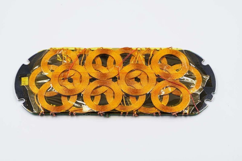
Wireless charging is conceptually simple. Two coils form an ad hoc transformer with the primary in the charger and the secondary in the charging device. However, if you’ve ever had a wireless charging device, you know that reality can be a bit more challenging since the device must be positioned just so on the charger. Xiaomi has a multi-coil charger that can charge multiple devices and is tolerant of their positioning on the charger. How does it work? [Charger Lab] tears one apart and finds 19 coils and a lot of heat management crammed into the device.
The first part of the post is a terse consumer review of the device, looking at its dimensions and features. But the second part is when the cover comes off. The graphite heat shield looks decidedly like an accidental spill of something, but we’re sure that’s just how it appears. The coils are packed in tight in three layers. We have to wonder about their mutual interactions, and we assume that only some of them are active at any given time. The teardown shows a lot of the components and even pulls datasheets on many components, but doesn’t really go into the theory of operation.
Still, this is an unusual device to see from the inside. It is impressive to see so much power and thermal management in such a tiny package. We wonder that we don’t see more wireless charging in do-it-yourself projects. We do see some, of course. Not to mention grafting a charging receiver to an existing cell phone.


Even the product name on the box is “Multi-coil wireless fast charging board”.
It’s a pretty complex design and the PCB inspection is thorough enough to give you an idea of its capabilities, but I can’t believe they measured only the input power and not the actual charging rate. So much thermal management suggests a significant power loss.
+1
Very nice tear down, very nice photos and chip identification + datasheets.
I still prefer a cable and tossing my phone away into the pile of trash on my desk.
I’m generally a cable person, but a proper wireless charge solution for those devices that are likely to come on and off charge really often or must be very very watertight does make sense to me, and can be surprisingly efficient in energy transfer..
This isn’t that though – the efficiency must be awful with all the other coils in the way of the correctly positioned one and the deeper coils being so much further from the target. What you want is a good registration indicator – something that visually means you put things in the right place, or better still a design that funnels the device(s) to the right spot for that one coil hidden behind the thinnest skin you can manage.
The coils “in the way” do nothing unless there’s a current loop. My guess is the charger enables those who resonate the best with the phones antenna, because the bane of near field power transfer is alignment.
My brother has an inductive cooktop that can to some extent heat wherever and only where you put a pan down, which it seems to do by cycling coils to find which one has the biggest power draw, and then using that one. (This based on moving things around on it while it’s running.)
Even if that in the way coil is an open circuit it will do something – as it will create some inductive current and losses related to to it.
I wonder if they could use the overlapping not optimal coils in a similar way to phase array beam steering so they are actually part of the power delivery… I have no instinct on exactly what would happen in this rather complex situation.
this is a reply to smellsofbikes:
try holding a coil of wire with 2 reverse-parallel LEDs (or bridge-rectifier and 1 LED) and resistor near your cooktop while cooking…
also the “pot-detection” can be “viewed” as a source of lower-power pulses when cookware not present.
everyone should try this before they are all gone, not designed right and the slightest glitch in the fan speed software renders the entire unit (including oven) completely error-ed out due to shorted output transistors. they will not be around long, too bad because efficiency is actually better when the pot heats the stove!!!
because if boiling water is 100deg.C., then why is the stove 500? its like a linear 5v regulator running from 25v == 1/5 = 20% efficiency.
too bad LEDs dont like operating at 200deg.C. …
Yes my first thought when I saw lots of heat management was lots of power loss ! I fail to see the attraction aside from people being simply TOO lazy to plug it in ! Of coarse there is the issue of contact failure also which is about the only thing I can see that makes this tech useful at all.
All this kluge design effort plus taking a loss on power transfer and probably significant RF interference (both of which become real issues if there are a billion of them all over the world) just so you don’t have to plug in a stinking USB cord…..
How is it a kludge? Did you read The Fine Article? You do know that field intensity falls with the square of distance, don’t you? Have you never had to (send a phone for) repair for a worn USB connector?
Stay tuned for the next episode of…
The Peanut Gallery
Inefficient power transmission.
It is basically an air gap transformer, if the gap is zero (and the coils are perfectly aligned and touching each other) then the maximum power transferred is probably about 70%. And as the distance between the coils increases the transfer efficiency drops off exponentially. So if you read between the lines of the info on the first link above “Input: 9-20V, 6A Max”, “Total output: 60W Max”, to me that would be throwing 50% of the power away. Should we really need to build 100% more power plants globally because some idiots can not deal with plugging in a cable. What is next replace power sockets ? *facepalm*
It doesn’t have to just be power transmission though – you can also use the coil transmission phase as part of the transformer from high to low voltages. I haven’t looked into the commercial branded options to know if any of them work on that principle, but if they do the transformer loss in the air gap becomes vastly less significant – as you were going to have to do a lossy power conversion anyway, so its turning what would have been 80-90% to 70% efficient perhaps (the numbers are arbitrary really).
There are some very good reasons to not have to plug in cables – like water proof devices, and devices for those with visual/motor impairments. You have to also realise that normal wear and damage to loose cables means they are likely to need replacement more than once which is actually a meaningful energy cost to make and ship – the more fixed charging installations should mean it lasts a good long time.
A well designed SMPS (Switched Mode Power Supply) can have an efficiency as high as 95%!
Lets look at what they are getting:
“Input: 100-120V~50/60HZ 1.7A” (~170W ignoring the power factor)
“Output: 5V3A, 9V3A, 11V6A, 20V4.8A” (15W, 66W, 96W)
~56% efficiency
“Input: 220-240V~50/60HZ 1.7A” (~374W ignoring the power factor)
“Output: 5V3A, 9V3A, 11V6A, 20V6A” (15W, 66W, 120W)
~32% efficiency
And that is before the 50% efficient using their air gap transformer.
So in reality overall they are getting 28% efficiency on 100V AC (I’m not even using 110V AC, that would be even worse at 25.7%)
Or 16% efficiency on 220V AC
The efficiency is dire.
Never said the efficiency was good, just potentially less bad than it sounds under those situations – I don’t know if such a situation is real for any wireless charging, but taking directly wall AC (or at least nearly directly- drop it down some for power limits in the tiny coils probably) wirelessly to the DC rectifier/final stage at the other end means overall efficiency isn’t that massively bad.
As all you end up doing is really comparing what is almost certainly a ferrite core to an air core (probably coupled with a ferrite core) and the same DC rectifying stage – its still going to loose to a cable, because of course it is, but not feeding it DC to turn to its variety of AC for transmission to then get turned back to a DC isn’t all that different to turning the AC straight to DC. Phone chargers and the like are generally not noted for their efficiency anyway, being the cheapest thing to turn AC to phone feeding DC the company can get away with selling/giving with the device…
As I have said here already I’m a cable person mostly, they are better. But wireless does have potential gains and uses.
Depending on on the technology, it can be a resonant coil transformer which deals with the efficiency issue by recycling the energy that was not used up each cycle.
A normal transformer simply reverses the field every cycle and consumes energy to push current through copper whether or not anything is picked up by the other coil. An air gap transformer is especially inefficient because it needs a ton of current to keep the field strength up at distance, so the secondary can induce any voltage from it.
A resonant transformer runs a resonant LC tank on both sides, which is oscillating by itself, so it doesn’t need to push that much current to keep the transformer going. Likewise at the receiving end, the resonant circuit means it can keep the voltage up in a weaker field because the oscillation can grow over many cycles, which further reduces the requirement for high drive currents at the primary side. If the distance between the primary and secondary circuits is relatively short, this can actually give a fairly high efficiency in the 90% range.
Or to put it otherwise, a resonant transformer has a higher Q factor than a regular inductive charger which has some active circuit element with significant ohmic losses in series with the transformer, doing the actual switching and reversal of current every single cycle. In a resonant transformer, the oscillating current is happening by itself in the LC tank, and the switching element is simply “topping it up” to keep it ringing, where by the I^2R losses are minimized.
100% more power plants? You really think phone charging consumes that much of our generation capacity?
Yeah it’s not great to have efficiency like that but… There are much large gains to be made elsewhere if you want to actually change something.
On earth there are currently about 5.27 Billion ACTIVE mobile phones. Compared with 7.2 million electric cars. Both could waste a lot of energy without legislation to force manufactures not to waste energy.
And there is talk of building inductance pads for electric cars and trucks. Now there’s a lot of wasted power.
You’ve never had a port fail on a tablet/phone? That is exactly what has failed the most for me. Hasn’t beena problem since I switched to wireless charging for 90% of the time. That saidI don’t have any trouble aligning things these days. I did back when I had an LG G3 (large phone and the chargers were small pucks) but nothing recently.
Every phone I’ve replaced except my first (the screen burned so much I couldn’t read it anymore) was because of the usb port failing and the phone no longer charging.
Current phone, LG, has a usb connector that has 16 surface mount and 5 through hole pins, and the surface mount section is completely surrounded by huge numbers of 0201 decoupling caps, so when I use a hot air pencil they start blowing off the board before the connector has reflowed. (tape with polyimide, sure, and then the polyimide pulls them all off instead.) I can’t use a hot plate because there are temperature sensitive components above the board on both sides.
I think inductive charging would be a big improvement no matter how inefficient. (And how hard could it be to make a recess the shape of your phone so it’s auto-aligned to the best coupling?)
The irony is standardizing the power port to be USB instead of the traditional barrel jacket. A USB connector was intended for computer peripherals and wasn’t designed for many thousands of insertion cycles in the first place, although USB-C now is, if you trust them to be made that way.
Also, the ports failing on phones is the manufacturer’s choice. The main problem is the connector peeling off of the PCB because the part is simply soldered on, and any amount of twisting and wiggling will do that. Old Nokias had the connectors on separate tiny modules that themselves had a simpler spring loaded connector to the PCB edge, so if you managed to destroy the connector it was actually quite simple to replace. Open up phone, pick the module out, place a new one in.
yes they interfere like hell because of the misalignment, it also doesn’t quite work as a transformer but more like a loose coupled inductive circuit. Harmonics are present far over 30 MHz and with some wire length make a nice wideband noise source.
I do not see much use in this complicated wireless charging gadget when a simple USB cable is sufficient for any brand Phone exept the fruit brand.
If you want to do fancy, then use a 3D printer to make a docking station or just plug an USB cable in your phone, wrap something aound it and smear some plaster around it and let it dry to make a docking station.
Then I’m very thankful it’s not up to you what innovations are made in the world.
And I am tired of not being able to find proper consumer products due to the so-called “innovations”.
A good docking station with physical contacts needs one or other (maybe even both) sides to have some float in them, or they will just never slide into each other cleanly. Look at laptop docking stations and they often have 3-4mm of play in x-y (as in something approaching 2mm from centred position) and a little in z with longer guide pins of some sort to help guide them together.
Don’t think you are wrong on cables being generally plenty good enough, but such a primative dock as you suggest will either not work at all or inevitably put stress on one or both connectors for a more rapid failure.
Children can’t permanently break your phone by unplugging it wrong, tripping over the cable, etc (they’re very creative in accidentally destroying things they don’t even use) if there’s no cable plugged in at all. :Tapping head meme:
The USB port has been the main killer of my family’s devices, so not having to use it is wonderful. (It also means you can actually use the water resistance too gently when on vacation in the before times.) We’ve got a USB-pd charger we sometimes use when charging while holding, and of course USB batteries, but any time sitting on the charger is time it’s not vulnerable to port damage. Also reduces wear on the cases – we use huge OtterBox defender cases that have flaps covering the ports, which sometimes wear out.
As for tripping over the cord, my bolting cat pulled my $160 original Amazon Echo down to the floor from the fireplace (only convenient location for it) and smashed it into a few hundred pieces. Since this, I use magnetically coupled charging cable adapters on EVERYTHING now.
It would be more expedient and environmentally more responsible to simply get rid of the cat. Cheaper too.
Though I can’t fault the cat’s intelligence for taking out the Echo.
OK. So my impulse was to say that it’s not the cat that is a danger to the environment, it’s clearly US. But I won’t do that. Oops! So is the environment for US or or THEM or for everything? But if you simply don’t like cats, then just say so, in which case you flunked the “humans are better” test.
It seems normal that cat owners are vigorously defensive about it and see cat-hating conspiracies in normal discourse. It’s weird and and a bit creepy.
But my statement was simply this: The cat is destroying things and causing you to purchase more manufactured goods, as well as costing you direct expenses in its care and feeding. Both the discarding and manufacturing of the goods have environmental costs. The simplest solution is to remove the agent causing the damage and expense.
These “magnetically coupled charging cable adapters” I guess it is the magnetically held together type, ie. Instead of a friction fit, or a snap in connection. The contacts are pressed together by a pair of magnets instead.
Such a magnetically held together connector wouldn’t have any of the disadvantages of wireless charging.
And to be fair, I would like to see more magnetic contacts to be fair. Downside is how trivially they disconnect, but sometime that is the feature, as can be seen with the echo killing cat.
I’ve tried some of those magnetic cables, they work reasonably well, at least for USB 2.0 stuff. USB 3 has too many potential conductors in the cables it becomes a mess trying to find one that is compatible with the device.
They are also using rather tiny pogo pins to fit in the footprint at the head of the cable, so are rather delicate, and being pogo pins probably not rated to all that many cycles even if you look after them well either… I’ve not managed to wear one of the 3 I got out, but have lost one on the first or maybe second trip in the laptop bag to damaged pogo pins – I think it was being attached to a fairly powerful magnet snapped the head down onto the bag surface at a rivet, and the weave bent em up… but really no way to know what managed to get in there and wreck em.
Are some better magnetic cable coupling techs – but non I am aware of suit the stupidly thin uncomfortable to hold craze that has taken over modern portable devices…
I’ve also added the magnetic couplers to virtually all the USB devices I need to charge/power but are not critical on data speeds (headphones, mice, Arduinos, and even phones, as I rarely connect to them over USB). The magnetic ‘bungs’ also stop the USB connectors getting full of pocketlint.
> when a simple USB cable is sufficient for any brand Phone exept the fruit brand
The fruit branded smartphones charge via USB since the very first iPhone 2007. It’s just that you have to use the included cable. And now we have USB-C – and even the fruit branded laptops charge via USB.
No iPhone ever has used a USB cable to charge.
The original iPhone used Apple’s proprietary 30-pon dock connector, newer models use Apple’s proprietary lightning cable instead. Neither of those proprietary connectors are USB.
Yes, you can get a cable with a USB-C connector on one end, a chip inside to tell your phone it’s a certified cable, and a lightning connector on the other, but that is definitively NOT a USB-C cable. Same with the A-to-lightning, A-to-30pin, etc. USB is a standard, those non-standard cables aren’t it.
i’ve long wanted to make a charger like this but without the goal of position-independence. i’m imagining a physical connector that mates….a female side on one end that is just the secondary wrapped around empty air, and then the male side would be either the primary or maybe just a ferrite core that is in common with the primary. i was imagining it to charge a hermetically-sealed bike light as like a 1cm diameter post that is 1cm high. so not small enough for a smart phone, obviously…though i would imagine it could be miniaturized, i don’t really know what the trade-offs are (transformers are always a voyage of discovery for me)..
it would still need to physically mate in a specific position, but it could be relatively insensitive to orientation. it would mechanically enforce its position requirement, without necessarily having a tight connector that is hard to insert. and, most importantly, it wouldn’t be subject to any of the costs of contacts — oxidation, gunk, or a point of ingress. and maybe this is naive of me, but i think it would be more efficient than the parallel windings with only a common air core that is the more traditional charger. that’s important in my book because heat is the thing that kills lipos and i consider the typical design of a hot (inefficient) coil 1mm from the currently-charging battery is just a complete non-starter for me.
the reason i never even tried it for the bike light project is that it turns out standard old micro usb is fantastic. sometimes you have to replace the cables but the jacks are basically indestructible, even if you permanently mount them a couple inches from a bicycle tire. combine that with the fact that water ingress doesn’t seem to destroy my lights (the only delicate component is a pushbutton switch, which i’ve also found to be perfectly reliable in this environment), and i just haven’t had any need to try anything different. i imagine i’m just lucky, but i’ve been building lights like this for a few years now and never had any problem with it the switch or micro usb.
Wireless charging seems so silly to be fair.
And since the efficiency drops with an increased distance between the coils, then a plate like this does add some additional distance for some of its coils. And this can’t be for the betterment of efficiency.
That wireless chargers are practically providing lack luster power efficiency in exchange for some additional comfort.
One could implement a contact based solution instead, and device makers have done that to be fair. But settling on a standard docking solution is apparently hard. (One could just specify that the two outer corners of the “bottom” edge of the phone should be charging terminals, and that these should be separated from each other by a minimum of X cm from the center of the device, then a charging dock would be fairly trivial to make, especially if the voltage supplied is to a standard, something that could be negotiated by NFC. In short, the charging dock more or less becomes one of those clamp based phone holders.)
But back to wireless chargers.
To a degree, I personally wouldn’t be surprised if it ends up illegal outside of a few niches.
Though, to be fair, wireless charging might already be illegal in the EU. (And this being the case from 2009, but it is more clear in the current directive, but as we can see bellow, not clear enough for me to write “are” instead of “might”.)
Since the 2019:1782 laying down ecodesign requirements for external power supplies pursuant to Directive 2009/125/EC of the European Parliament and of the Council and repealing Commission Regulation (EC) No 278/2009 (the name of the actual directive that has entered into force.)
This directive does have minimum requirements for an external (mains) power supply. A power supply under load needs to be at least 67% effective. (if bellow 49 watts. (bellow 1 watt, it is 16% on the other hand.))
If one builds a wireless charging station with an AC inlet and no other outputs. Then it is clearly illegal due to not having satisfactory efficiency. (I suggest actually reading the directive here.) Giving it some other outputs only makes it a bit more dubious, might still be illegal since one of its operation modes isn’t sufficiently efficient.
If a wireless charger that isn’t connected to the mains. (“mains” by the directive means the electricity supply from the grid of 230 ± 10 % volts of alternating current at 50 Hz. (Actually, EU mains is 230 +10 or -6 % It is on paper “harmonized” and in practice it is close enough. Ie, all EU countries shouldn’t change what they currently use. But back to wireless chargers))
Then one technically don’t have to care about this directive. BUT, one might still need to conform with it.
Since the directive looks at the efficacy from the mains, to the “primary load”.
Anything we add in-between the mains and primary load will contribute to a lower efficiency, eventually, that efficiency isn’t satisfactory. We could argue that a sufficiently long cable on the low voltage side will eat into efficiency. But we should likely look at realistic operating conditions.
But the directive never puts forth a definition of what it means by “primary load”, is it the next load in the chain? Or some other device further down our chain?
Considering how the directive puts forth a definition of what “mains” power is, and practically every other technical term we could question as well. So why didn’t it define what can be considered the primary load?
The directive is though making long lists of example loads, where non is a device mainly concerned with supplying power to something else. (If we make a technically exception to stoves and other heaters.)
There is however an exception for “battery chargers without power supply function.” But, one can place a phone on a wireless charger and still use the phone for other things than waiting for it to charge. And since the wireless charger isn’t solely powering the battery, but rather the whole device, then the charger is arguably providing some power supply functionality. However the wireless charger is typically not mains powered so not inherently subject to the directive itself.
I would argue that wireless chargers are currently legally dubious as a whole. Since we don’t know what the directive means with “primary load”, so we don’t know if the wireless charger is part of our power supply solution or not.
If the wireless charger is considered part of the power supply solution. Ie, between the mains and our primary load, then the wireless charger does eat into overall efficiency. And since there currently is no wireless chargers with efficiencies above 67%, then it can’t be used legally in practice, at least when connected to a mains connected power supply. (Non mains power sources aren’t covered by the directive after all.)
Though, realistically, the wireless charger would need to be a lot more efficient, since we also have the efficiency of the power supply, and voltage drop in realistically long cables to consider. (and yes, even the cable would matter if our primary load is on the other side of it. And here the directive could just state a simple, “cable of 100 milliohm.” and call it a day, since most normal cables have resistances around that or bellow.)
(One could though argue that the magnetic field stores energy in it, and that this technically makes the charger into an exceptionally short term UPS, and therefor except from the directive. (this here is a joke.))
I for one would like to see a graphic of the EM fields and some closed-form Maxwell EM field equations of its operation. That’s got to be crazy more complicated than any multi-body celestial motion equations.
Lotsa EM fields
https://bilder3.n-tv.de/img/incoming/origs22630906/186279849-w0-h0/imago1003194852h.jpg
https://apps-cloud.n-tv.de/img/22631268-1624167212000/o/2436/2436/bg-por-ger-4-.jpg
https://apps-cloud.n-tv.de/img/22631273-1624167214000/o/2436/2436/bg-por-ger-8-.jpg
(Sorry. Its hot here.)
You forgot the Maxwell equations.
A difference exists between power thrown away vs temporarily stored to be recycled at a later time. Resistance vs reactance.
That isn’t really the case in regards to wireless chargers. A fair portion of the energy is lost through resistive heating in the primary coil. And a fair bit escapes as EM radiation. In short, there isn’t much being reabsorbed by the driver circuit itself, if it even attempts such to begin with.
The thumb rules for inductive loads on the power grid doesn’t really apply for this type of appliance.
The famous inventor (and the original wireless power transfer researcher, you may recall) Benjamin Franklin, is remembered for having said (something like): “Those who would give up essential efficiency for the sake of a little temporary convenience deserve neither.”
Over a decade ago my Palm Pre had wireless charging all figured out with magnetic alignment. It was fast and should of been the future of charging but it was lost in patent hell.
Magnetic plugs guys! They are wonderful!
I bought 2 cables and one plug, the plug stays all the time on the phone, and one cable stays at bedside and the other on my desk. Effortless plugging and unplugging, no trips sending the phone flying, no wireless power loss. And you can buy the cable or the plug, or a kit. And they are cheap, just a couple bucks on your favorite Chinese marketplace.
I even intend to buy some to give out as birthday gifts, it’s a cheap thing that seriously increases your quality of life.
just saw one of these installed on someone’s phone about a week ago – does seem like the way to go for such gadgets – probably more so than wireless charging
“and a lot of heat management crammed into the device”
Kind of says it all about wireless charging
The irony of wireless charging is that it requires a lot more wire.
Look at it.
Do I see enormous amounts of un-reflowed solder paste in the last few photos?
Yeah I too was wondering what all that gunk was!
As for efficiency, well why not look at the DC power in versus the capacity of the phone battery in mAh.
And compare it against using a direct USB charge cable instead?
That measurement might tell you the efficiency much more directly than the hypotheses spouted above….
They say in the article on charger labs. It’s the remains of the heat conductive silicone.
I think it would have been easier and cheaper to have 1 coil with an X-Y bed to optimise the position of the coil based on the measured power-transfer.
Or suspend the coil on springs and align it using magnets?
Or simply magnetic cable/contacts. Like the Pebble watch. Should work great on phones as well. If you want to be fancy, use some robotics to plug the contacts when you throw you phone on the charger.
The whole idea of wireless charging is to be able to throw the phone on the charger and not have to fiddle with a plug. Wireless charging is just one kind of solution to that. Could also have a robot to plug the charger cable in the phone.
Seems like wireless charging is mainly chosen as a solution because it looks fancy.
Hmm maybe I should write up some of my toys. They’re mostly budles of compenents held together with kapton (one day I’ll commit to a PCB), but I’ve started putting Qi receivers in them so that I can make the case waterproof. I use magnets to help with alignment, so to a large extent I can plob the device down on the charger and it’ll align itself and charge.