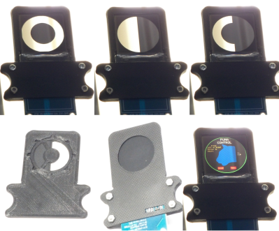
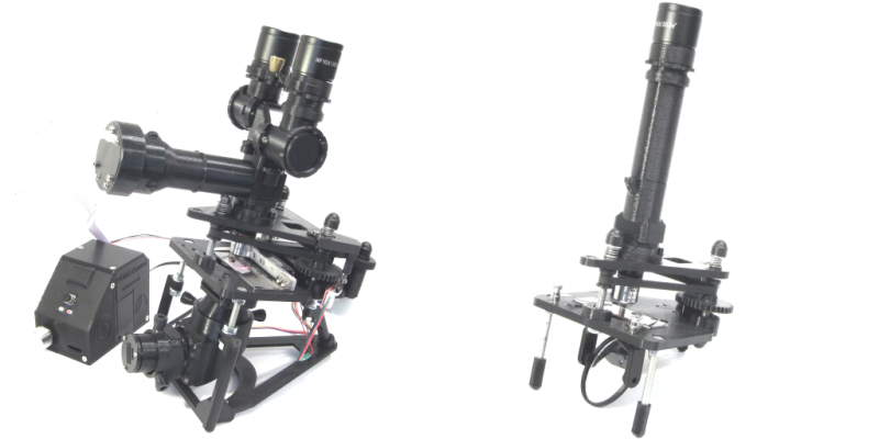
What do you get when you cross a day job as a Medical Histopathologist with an interest in 3D printing and programming? You get a fully-baked Open Source microscope, specifically the Portable Upgradeable Modular Affordable (or PUMA), that’s what. And this is no toy microscope. By combining a sprinkle of off-the-shelf electronics available from pretty much anywhere, a pound or two of filament, and a dash of high quality optical parts, PUMA cooks up quite possibly one of the best open source microscopy experiences we’ve ever tasted.
GitHub user [TadPath] works as a medical pathologist and clearly knows a thing or two about what makes a great instrument, so it is a genuine joy for us to see this tasty project laid out in such a complete fashion. Many a time we’ve looked into an high-profile project, only to find a pile of STL files and some hard to source special parts. But not here. This is deliberately designed to be buildable by practically anyone with access to a 3D printer and an eBay account.
The project is not currently certified for medical diagnostics use, but that is likely only a matter of money and time. The value for education and research (especially in developing nations) cannot really be overstated.

The modularity allows a wide range of configurations from simple ambient light illumination, with a single objective, great for using out in the field without electricity, right up to a trinocular setup with TFT-based spatial light modulator enabling advanced methods such as Schlieren phase contrast (which allows visualisation of fluid flow inside a live cell, for example) and a heads-up display for making measurements from the sample. Add into the mix that PUMA is specifically designed to be quickly and easily broken down in the field, that helps busy researchers on the go, out in the sticks.
The GitHub repo has all the details you could need to build your own configuration and appropriate add-ons, everything from CAD files (FreeCAD source, so you can remix it to your heart’s content) and a detailed Bill-of-Materials for sourcing parts.
We covered fluorescence microscopy before, as well as many many other microscope related stories over the years, because quite simply, microscopes are a very important topic. Heck, this humble scribe has a binocular and a trinocular microscope on the bench next to him, and doesn’t even consider that unusual. If you’re hungry for an easily hackable, extendable and cost-effective scope, then this may be just the dish you were looking for.
Thanks to [linus] for the delicious tip!


“PUMA cooks up quite possibly one of the best open source microscopy experiences we’ve ever tasted.”
Did your word processor get the article mixed up with your article about the coffee maker?
B^)
Or do we just chalk this up to another WordPress “feature”?
B^)
On further reflection, referencing “taste” and “cooks” in an article about a pathology…
Ewww!
B^)
Maybe it’s not to your taste, but it wets my appetite.
Add the code to stabilize the shaky image/video and worry not about the physical aspect being vibrated.
As much as I would love to like FreeCAD … It’s just ages behind something like Fusion 360. I regularly check in because I really want to use FLOSS software … but always come back to F360 in the end :-(
I think is a matter of what you learned first. I tried F360 coming from Rhinoceros and found it stupidly obtuse, and 3 hours of tutorials barely left me struggling to do the simplest things.
Installed FreeCAD and 10 minutes later I was whipping (admitedly terrible, but got better) models.
I still go back to my old (ie: needs windows 7) copy of rhino for some things (FreeCAD doesn’t do very well things like text extrusion) but not for much more.
This was exactly my experience, even coming from Rhino too. F360 has ok tools, but is not a go to tool for me.
I’m with nekoplanetd here, for many things I would say FreeCAD is better than Fusion, not really any features one has the other can’t do easily (any more at least), just varied degrees of easier to do a very specific operation in this or that one…
Its like any tool you have to learn how to use it right – and its that using it right that really matters – take Martin from Wintergatan and his MMX marble machine, through its development you have seen a vast increase in his skills and use of the CAD tool, as now he really is using it ‘properly’ – following better practices than before, making the whole thing much simpler to change, the design process of something so complex smoother.
I am being sarcastic here … but:
> ot really any features one has the other can’t do easily (any more at least)
… like defining the distance between two parallel lines? ;-)
(yes … you can use an additional construction line, make that orthogonal to both lines and define its length … but come on that such a common task)
I actually started out in OpenScad, then tried FreeCad for a while until somebody convinced me to try F360 … since then I give FreeCad a try every once in a while. And I can definitely see that it is getting better, but for me it’s a PITA :-(
If you use the “distance” constraint, you can’t select the two lines themselves to set the parallel distance. However, as long as the lines are already constrained to be parallel (with the “parallel” constraint), you can set the distance between the endpoints of the two lines, or between an endpoint on one line and the other line itself.
The one thing you can’t do is select one line and then another to set the parallel distance, which is what you were talking about. But since you can do the same thing by just selecting the endpoints instead, it’s not a deal-breaker for me.
Hmm … But that only works if your line starting points are … eh … orthogonal? to each other. If you want to build a trapezoidal shape that does not help.
To be clear: I am all for FLOSS, F360 is literally the only commercial software I use regularly.
I do the same regularly. There are some longstanding bugs that really irk me, and the forum has a bad case of “works for me”.
Try FreeCAD link branch by realthunder. It’s a joy to use, with the topographical naming problem (among other bugs) fixed, and a couple extra features as well.
Ah, and he has an Assembly workbench. Noted, thanks!
This is a really neat concept, not 100% sold on it being worth it, but definitely worth thinking about.
Certainly a great step on the way to any very specialist microscope you might want to build into something else too…
But for me I think designing for 3d printing is the wrong idea for a microscope, design such that its easy to laser/water jet out of sheet stock and off the shelf tubes and threaded parts seems like a better idea to me – a more suitable material selection is then possible, especially for the ‘travel’ pack breaking it down type use case.
All that said I might just have to make one, or a modified version for my needs, as I have been looking for magnification options, and it does look like a well thought out starting point at the very least…
Designing this kind of thing assuming the availability of a 3D printer is already hard enough, without tackling the complexity of dealing with parts that have only locally available dimensions, thread sizes, unknown tolerances, etc.
3D printers are now cheaply and widely available anyway. Heck, a decent 3D printer costs less than most name brand power tools.
I would argue basics like PVC or metal tubes can be bought in nearly any dimension pretty trivially while having some pretty much globally available common sizes, and threaded parts need not use the same thread just fit through the same hole size, though again threaded parts are pretty standardised globally as long as you don’t deliberately use some obscure old thread, or highly specialised super fine thread…
Sure budget 3d printers are now also common, but that doesn’t make basic raw materials that are nearly globally universal hard to get or use in this role, and I would argue designing around using mostly if not entirely a better material selection actually makes life easier – don’t need to bulk out and pad so the 3d print has some hope of surviving, just use off the shelf threads etc.
I’m not knocking 3d printers, love ’em they can do great things, but printing out big flat sheets with a few holes in and long featureless tubes is just silly. Maybe you still use some 3d prints for the things they are good at, strange geometries, ‘precision’ adaptors, but this whole thing like this seems like a bad move – so many structural parts made in relatively weak and flexing plastic, and taking a very long time waiting on the print – those big sheets in the base could probably be cut and drilled entirely by hand from a paper template in less time and getting a better structural result for instance. and the relatively delicate long tubes would take seconds to cut and sand to length in any material – maybe you still have 3d printed shapes at the end to make tube fit optic or whatever (as machining those bits would require a lathe and some skill with it), but its a much stronger, quicker and possibly cheaper result…
Somewhat unrelated, but since building my Voron 2.1 I am pretty convinced by the “3d printed parts as ‘glue’ for off-the-shelf rods and rails” design philosophy. This summer I build a vertical-axis wind turbine using aluminium rods where I can and 3d printing for the blades and connector parts. This worked incredibly well. (except for there is basically no energy to be harvested from a 0.6×0.5m vawt :-) )
My point was that the more constraints, the harder a problem is to solve. 3D printers remove all sorts of constraints, so it only makes sense to solve that problem first and then tackle the additional constraints in a v2.0 (or let someone else fork your design and tweak it).
Any chances of a similar approach to a stereo microscope? I’ve no idea what it takes to make it zoomable or parfocal, The HUD would be amazing for troubleshooting / reverse engineering.
You mean like the stereo configuration that’s in the header photo on this very article?
That’s binocular – focusing from a single viewpoint, then splitting the image for the two eyepieces. Stereo microscopes look at the specimen from two angles to provide depth perception, and generally have lower magnifications (say, 3-20x) and greater depth of field.