A while back, [Heavydeck] remembered stumbling across the worst CAD package ever, which is a schematic editor whose existence was purely intended for use to make quick circuit sketches for documentation, presentations and the like. All good. But, being based on low quality JPEG graphics, which when blown up to projector size on a big screen, they look really rough. After deciding that the original nasty, clunky interface was just nasty and clunky enough, [Heavydeck] then proceeded to reimplement the idea over the course of an afternoon, and came up with Kludge (possibly the second worst CAD package ever) making an actually useful tool even more useful.
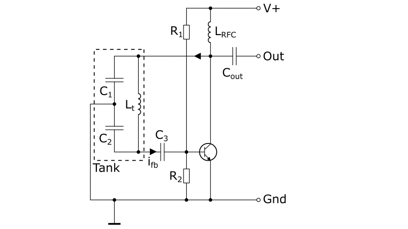
You see, whether you make website content, YouTube tutorials, or just need to write technical reports, if you’re in the electronics business, you’re going to need to make high-quality editable schematic images at some point, and Kludge might well solve some problems for you. Kludge lets you do so many things; you can save a schematic, you can load a schematic, you can even export it to an SVG file. Actually, that’s all you can do, but it is actually just enough. Once you’ve got an image as an SVG, you can whack that into Inkscape to add some more details and you’re done. We demonstrate this with the image above, which was not annoying at all to create.
So here’s to Kludging your way around a problem, and hoping that the somewhat limited symbol library may expand a little more in the future!


Or you can use Falstad’s circuitjs :-)
Was awesome 10 years ago and still is. Helped me design or try many circuits. It can even simulate Chua’s chaos oscillator, with some tunning! I see it as proof that it’s accurate enough for almost everything.
CircuitJS is really great. I wish I’d known about it when I was teaching.
It is incredibly handy to build a circuit with virtual o-scope and logic probes and then send it to someone as a clickable link. No install, no login, just pure and simple.
Works OK but without labels on devices how do you specify values?
Since it’s purpose appears to be to create a one-time schematic, presumably you take a screenshot and then add text in a photo editing program (Inkscape is mentioned), or just add them in Paint.
Depending on resolution requirements, a printscreen copy/paste based solution just doesn’t always cut it. And sometimes printscreen based solution leave you with an undesired background or scaling artifacts. So I can imagine the need for such a tool.
That’s what the svg is for: add whatever in Inkscape. Vector graphics, not bitmap.
The one called the “worst” looks like it could be implemented on an old pre-x86/x88, 8 bit computer with tile based graphics.
I think I even did a basic PCB drawing CAD in those days (late70’s – early 80’s) not that I could do anything with the image when we only had dot matrix printers but it was impressive to look at a PCB image from a dot matrix.
How do you place a tile? I drag a tile into the “Grid” area and drop it, but nothing happens. Browser is latest mainstream Firefox with no blocked ads or scripting.
Looks like you click a tile, which moves it to “Current tile”, then you click in the grid (not drag), and whatever is in current tile snaps to the appropriate spot on the grid. So it’s click-and-click instead of click-and-drag. ;)
@Assad+Ebrahim says: “Looks like you click a tile, which moves it to “Current tile”, then you click in the grid (not drag), and whatever is in current tile snaps to the appropriate spot on the grid. So it’s click-and-click instead of click-and-drag.”
Yes you got it, congratulations. I didn’t see that explained anywhere in the instructions. The click to select then click to paste feels clunky and unintuitive to me, but I might get used to it over time. Direct actions like delete, cut, copy, paste, flip, rotate, etc., do not exist at all. Everything requires multiple clicks and a LOT of page scrolling. The fundamental problem though is that there’s no integrated tile editor, so no new parts. But the price is spot-on ;-)
Agree, integrated tile editor would be best new feature to allow new parts.
Second best new feature would be text tool to add part values and other annotations… :)
I’m doing both in an export step (screenshot to mspaint). Could also export SVG to Inkscape.
Using Kludge’s lamp symbol as generic placeholder, then dropping on top the desired symbol (eg. speaker) from here: https://www.istockphoto.com/vector/set-of-electronic-circuit-symbols-gm602316366-103526411
Here’s an example (left image) documenting a low-cost but awfully documented £9 function generator:
http://mathscitech.org/articles/electronics#xr2206
Might as well use LTSpice if you don’t need to make a PCB. It can do simulation to see if the circuit turns out to be any good.
Interesting timing. A friend “elsewhere” just mentioned https://ctan.org/pkg/circuitikz – a tool for drawing circuit diagrams in TeX/LaTeX (or something like that.)
I always thought Eagle is the worst ECAD tool ;)
I’m not sure why anyone would hate Eagle. Personally, my ranking from best to worst that I’ve used goes Eagle, Altium, Orcad.
For a while my coworkers writing datasheets were required to use _visio_ to generate their schematics. I mean, we’d do our schematics in an actual EDA program and do our simulations and generate pcbs and everything like that, but when it came time to release the datasheet, someone would have to redraw it in visio because the datasheet release people needed vector artwork and that was the only format they accepted.
Having done this a few times I’m totally suggesting it as the worst schematic entry tool.
I thought DaveCAD was the worst.
Thankfully you (or the rest of humanity), haven’t seen RenCAD yet!
B^)
So what would be a suggestion for the BEST application that does this? I looked around repeatedly for a simple software over the last few years while weekly drawing wiring schematics for connecting custom control systems for use in water to water geothermal heating systems. I wasn’t designing the electronics, timers, sensors, etc, just drawing the 24V AC (common in the US for the past 50+ years) interconnections between them and at most dropping up to 5 or 6 general purpose relays in to create interlocks etc. Everything I found was geared to building electronic/PCB circuits where you could simulate etc and therefore had to select specific components and/or was overly complicated for the task (like everything mentioned in the comments here so far). These diagrams weren’t to be used by EEs, but installation technicians, so just old US style schematic showing terminal blocks on devices and interconnecting wiring between them output to a .pdf or other doc file… Ended up drawing by hand and scanning.
Any thoughts?
For a lightweight schematic capture program, I use TinyCAD (https://www.tinycad.net/Download). In comparison with KiCAD, Eagle or AutoDesk, it is TINY (20MB), quick, easy, no fuss, has plenty of design library elements, creates PCB netlist, and is free.
I’ve seen other complaints about “very good” CAD packages (from an engineering PoV) not being able to produce “publication quality” drawings, and I’ve always been a bit surprised that there isn’t an add-on that re-formats the CAD formats to something more printer-friendly (ie .svg) It doesn’t seem like it would be that difficult; most of the info is already there in some internal vector format; I’m pretty sure that I could get EAGLE’s ULPs to do a decent job, if I understood those other formats and the needs of printers. I can’t imagine that KiCAD’s extension language (python?) is any less capable…
It’s probably just that the people who understand CAD internals and extension langauges never talk to the people who understand graphics and printing :-(
DaveCad Rules! : )
I have been using ExpressPCB for that for over 20 years. Sometimes I use it for mechanical drawings too, tho it sucks pretty bad for that in most cases.
Do you mean ExpressSCH? I have both installed here. I used to use ExpressPCB for in-house PCBs. It doesn’t export anything that is useful to a PCB house but it can print.
The language here is totally lost. We start with “CAD” in the title then give a picture of a circuit diagram and then proceed to talk about “schematics”. No wonder modern engineers generate a glorified Bom netlist and call it a schematic.
A circuit diagram shows every single connection as a point to point “wire” from one component to all the others it’s connected to, this includes power rails.
A schematic (general term also used outside of EE) is much the same except power rails or not completely shown but insted have a symbol (Ground / Vcc) and a label to indicate a connection. Data and address buses are not shown as 8 or 16 etc connections but are instead shown as thicker lines with all the bus elements. This thicker line still goes to all the components that access the bus.
A netlist is a simple a list of all the connections to each of the components on the Bom. All to often I see a diagram of all the components with each component connection simply having a label that indicates the netlist connection it has: This is NOT a schematic OR a circuit diagram in ANY way. It is simply a glorified (itemized) netlist.
A circuit diagram or at least a schematic is essential for fault diagnosis and repair. A netlist is useless for this.
Lets say you have a signal line shorted to ground. I circuit diagram will simply show every connection that signal line has making it easy to test at each point. With a netlist you have to read through every label of every component looking for connection points.
Now say you have one signal line shorted to another. Good luck with a netlist!
Nice. Say what you mean, and mean what you say. The art of nomenclature! A higher state of Enlightenment, often practiced by object oriented engineering types, at the utter disgust of subjective freelancers.
Noooo. BobCAD is the worst. Buggy. Ancient architecture. Expensive (for what you get). Fusion or OnShape beat it by a mile.