There’s a lot to admire about LED matrix projects, which more often than not end up looking really cool. But most of them rely on RGB matrix panels sourced from the surplus market, and while there’s nothing wrong with that, building your own tiny, tileable LED matrix panels makes these builds just a little bit cooler.
There’s a lot to admire about these matrix panels, not least of which is the seamless way they tile together. But to get to that point, [sjm4306] had a lot of prep work to do. He started with a much simpler 5×7 array, using the popular WS2812 RGB LEDs on a custom PCB. With a little practice under his belt, it was time to move to the much smaller SK6805 LEDs, which were laid out in an 8×8 matrix. The board layout is about as compact as it can be; [sjm4306] reports that it pushed the PCB fab to their limits, but he ended up with LEDs spaced perfectly on the board and just enough margin to keep consistent spacing in two dimensions when the boards are adjacent to each other.
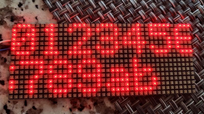
Assembly of the boards was challenging, to say the least. The video below shows that the design left barely enough room for handling the LEDs with tweezers, and some fancy finagling was needed to get the boards on and off the hotplate for reflow. [sjm4306] says that he’ll be exploring JLC PCB’s assembly service in the future, since each board took an hour for him to assemble. But they look fantastic when daisy-chained together, with no detectable gaps at the joints.
With matrices like these, the possibilities are endless. We’ve even got a whole list of LED matrix projects over on Hackaday.io for you to check out.


I wonder what would be the best way to have a black pixel. The problem of most of this diffused led matrices is that they look white-ish when turned off. Is it enough to use a dark diffuser or do you need some kind of polarizing filter like lcd display uses?
I would cut a mask on a CNC with hole for each LED, and paint it black, so LEDs are recessed and won’t illuminate each other, then cover it with acrylic glass. One could cover the glass with one-way mirror foil, like in infinite mirrors.
i was going to saw this. The leds package being white is the biggest part, but the pan that the leds actually sit in being white cant be fixed so recessing it so light is less likely to fall on the led would be a pretty good solution. Or we could over engineer it and use a black/white monochrome LCD panel as a mask and black out the pixels when they are off.
I needed square “pixels” for my diffuser, so I actually 3D printed a grid in black PLA that works great for blocking light from the neighboring LEDs.
There’s often no telling where rabbit holes will take one. I haven’t downloaded the board files but was curious about the pixel density. In the lighting industry we have commonly available P5 and P10 panels with respectively five and 10 mm between LEDs and there are even readily available P2.5 panels with LEDs 2.5 mm apart. The latter appears to be quite similar to this effort. In the holiday lighting niche hobby, P5 and P10 panels are becoming quite popular with numerous 8 ft x 4 ft assemblies (assembled from 14 in x 8 in sub panels containing 64×32 LEDs) showing up in home outside holiday displays. These panels are driven by, quite often, either raspberry pies or beagle bone make your controllers connected to various hats or interfaces such as Colorlight.
A link for ordering parts to assemble panels of generally arbitrary size is the website (I’m only a customer): http://www.wiredwatts.com/build-a-matrix-kit
Using “smart” LED with internal controllers is fine… until you put a lot of them in series. After maybe 30 or 50, problems start to pile up. 100 LED is the refresh rate drops. More, and ANY problem breaks the serial link chain… Says the guy who once had to built a 42m² pingping screen.
Depending upon what you consider an adequate refresh interval, the hobbists are getting generally 40 frames-per-second with tens of thousands of “smart” addressable LEDs. Check out any of the thousands of holiday lighting shows that are exclusively using digital pixels, mostly set to music. Here’s just one example from 2015 (state of the art in the hobby has progressed considerably since then):
https://www.youtube.com/watch?v=90oZ52M4IC0&t=5s
And this one is from last year’s Great Christmas Light Fight:
https://www.youtube.com/watch?v=H_rTv-hSmZg
Depends on the controller of the led.
What you describe sounds like classic WS2812 headaches. They are slow (800khz) and get more sensitive to corruption the longer the string gets as even the tiniest jitter can corrupt the data. As a result you must use a microcontroller that can update the leds without interruptions. At 30 refresh cycles per second for a display panel the limit is seen as 1024 leds per string. They are super cheap though and just need a single pin.
On the other extreme there are Clocked leds that communicate as fast as their internal shift registers and/or the host controller can clock in data. On which i’ve seen some reliably reach 32Mhz. At 30hz refresh that theoretically allows for 33.3 thousand leds per string. The cost though is that these leds are often slightly more expensive than your typical WS2812 and will need an extra pin for the Clock-signal. Optimally you would connect them to a SPI interface.
Most of them have clock in and clock out to similar to their data lines. I’m not sure if it’s necessary or not, it’s possible that they propagate clock after they shift their bits in to match up with their data out.
In any case, all the one’s I’ve seen have 6 pins (Vdd, Vss, Ci, Co, Di, Do).
Correct. vast majority of addressable led models on the market are indeed clocked. It is a simple, faster and reliable way of control. However a reality is that the specific led that dominates the market in nearly every application is the by now ubiquitous WS2812 which uses a timing based single-wire interface. Even my computer’s motherboard has a header specifically for controlling the WS2812.
One the CI/CO. It is necessary for a clocked addressable led intended for chaining to also buffer the clock signal in order to avoid parasitics and delays ruining your day.
The alternative would be to have a single host controller provide a clock signal to literally hundreds to thousands of shift registers at the same time. All those input parasitics would add up real quick and severely deform the clock signal into resembling a sine wave,at worst overload the host controller and introduce a real risk of timing errors leading to corruption due to the propagation delay inbetween each led.
is possible send data trought this led?
for example camera+led panels and 2km distance
I got several of 8×8 WS2812B LED matrix that are just 2.5 by 2.5 cm on tindie here ->https://www.tindie.com/products/microinventions/ws2812-2020-8×8-matrix-2525mm/ and they work nicely as a text scroller. One thing to point out is that these leds heat up a lot if used at high intensity.
Adafruit have something very similar to this using APA102s, which if I remember right are very similar to the SK8605s in the article, and have some benefits over the WS2812s. Still, sometimes the fun and learning are in doing it yourself instead of buying a pre-built, and it looks like the Adafruit boards wouldn’t solder together in rows like sjm’s would (that seems like a strange omission?).
This is a great project. And yes, wholeheartedly agree with the idea to have a fab house populate them. I ended up with a project using about 1,000 of them, placed at somewhat arbitrary angles. I don’t have that level of patience with vacuum tweezers.
I also wrote up a bunch of data on the current usage of these: https://github.com/alorman/sk6805-1515-info
I built a project like this out of prefabbed LED matrices (I’m terrible at code so splicing together examples was a trial by fire I’d soon like to forget) but one thing that disappointed me is how many of these matrices are awful in the daytime.
I wanted a sign that could be seen from outside through window but I can’t seem to find anything that is rated for that, even if I have to pay more and supply more power.