One of the core features of the scientific community is the concept of “peer review” where any claims made by a scientist are open to be analyzed and reproduced by others in the community for independent verification. This leads to either rejection of ideas which can’t be reproduced, or strengthening of those ideas when they are. In this community we typically only feature the first step of this process, the original projects from various builders, but we don’t often see someone taking those instructions and “peer reviewing” someone’s build. This is one of those rare cases.
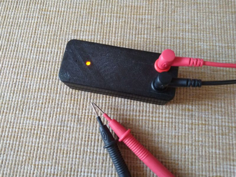
[oxullo] came across [Leo]’s original build for the ultimate continuity tester. This design is much more sensitive than the function which is built in to most multi-meters, and when building this tool specifically some other refinements can be built in as well. [oxullo] began by starting with the original designs, but made several small modifications. Most of these were changing to surface-mount parts, and switching some components for ones already available. Even then, there was still a mistake in the PCB which was eventually corrected. The case for this build is also 3D printed instead of being made out of metal, and with the original video to work from the rest fell into place easily.
[oxullo] is getting comparable results with this continuity tester, so we can officially say that this design is peer reviewed and tested to the highest of standards. If you’re in need of a more sensitive continuity sensor, or just don’t want to shell out for a Fluke meter when you don’t need the rest of its capabilities, this is the way to go. And don’t forget to check out our original write-up for this tester if you missed it the first time around.


Sounds like some big innovation but we’ve been doing stuff like that on Elektroda forums, Elektronika Praktyczna and Elektronika dla Wszystkich newspapers for decades. Oh snap I must be getting old despite being just 24.
Could Practical Electronics be an english language equivalent ? Unfortunately, I can’t read polish, but from the pictures, it seems cool !
Yes it’s translated as Practical Electronics it is aimed mostly for advanced users, while Elektronika dla Wszystkich is “Electronics for everybody”. Website for practical electronics: https://ep.com.pl/archiwum
From last month: DiY powerwal from a e-scooter. Project black swan, a one way, secure, Internet messenger. I2C relay etc.
Google translate does a pretty good job, apart from wording in graphics.
Yeah this is elektroda energy for you, good thing OP (specjalnie z dużej litery) had not used arduino
I could use that. I have a good multimeter, but if you only need to do continuity check (like many times i do), it’s a bit bulky. Wouldn’t be too much to throw this to the test bag.
Test for heavy power cable wiring whatever ohms, OK. Test for a small signal switch, less than an ohm OK. Tester must be able to send Morse at 10 words per minute or faster. No delay on or off, some multimeters can’t do this on their beeper. When testing a solid 3 seconds is valid, a brief beep is not. Longer whilst shaking and bending to hear the tiniest glitch of failure. Sharp (danger) needle tip probes not those plated blunt probes supplied with all meters pierce insulation flux paint etc for real meaningful readings.
Some 35 years ago I once worked with a home brew circuit (made by someone else) that used the measured circuit resistance to generate a tone. You could clearly hear the difference between 1Ohm and 3 Ohm, and I think it’s upper range was somewhere around 100 Ohm, but that’s of course adjustable in a home brew circuit.
I guess that circuit may have been published in Elektor, in the ’70-ies or ’80-ies.
Oh that’s a nice idea, I might steal that.
I found a bug in some of the fluke meters when you come out of continuity mode, fixed in version 5. https://youtu.be/ItSNABMokuk