One of the great things about plastic is that it can be relatively flexible. We see things all the time that snap together, but when 3D printing, you don’t often run into snap fit designs. [Engineers Grow] has a video to help you design snap fittings that don’t break.
In the first video that you can see below, he covers three parameters that can help. The first is the length of the snap element. Secondly, the undercut size can be reduced. You can also try making the snap; as thin as possible, although in the example he went too thin and wound up breaking the snap anyway.
The final suggestion, covered in detail in the second video below, is to change the material you use. The key parameter is known as elongation at break. For PLA the typical value for this is 8%. ABS is 10%, PETG is 24% and Nylon is 100%. Simplistically, you could assume that a PETG piece could deform up to 25% before breaking. That may be true, but it will permanently deform long before that. The video suggests using 10 or 15% of the value to assure the part doesn’t lose its shape.
In the third video, you’ll learn, too, that print orientation counts. Making the hooks grow off the build plate leads to a weak hook as you might expect.
We’ve looked at the mechanics behind these before. You can find a lot of detailed technical data about joints, too.


Even though PLA might not break when printed in the right orientation, the hygroscopic nature will make it brittle and it will tend to deform over time more than PET(G) or ABS, when exposed to the bending stresses.
I always hear this, and I only have _one_ counterpoint: The first print I’ve ever done, the cat example that came with the Monoprice Mini 2 or whatever, printed in PLA, was placed in a flower pot, on a window sill in full sunlight, in 2018. It’s a flower pot, so it gets plenty of water, and admittedly it doesn’t have moving parts, but I inspect it now and then and I can’t see or feel any degradation.
Only one data point, but I’ve since printed lots of structural parts with zero failures that wasn’t a design fault.
Do we have any articles I can read up on this? With more data?
huh. i wonder how much of that is because of the PLA you used? or if it’s because you aren’t subjecting it to daily forces?
i have used formfutura easyfil pla, which i love, btw. one of the best things i have made is 3 sinks in my house now have specialty soap dishes. but in this role, they last about 2-4 years before they become too brittle for the structural loading of a new bar of soap. they’re enough of an improvement over non-specific soap dishes that i just print them again.
i guess the soap may also be bad news for them. but one way or the other, they definitely over time all turn into a brittle mess.
otoh, i printed a sink drain strainer 8 years ago out of a much lower quality PLA (it was brittle before it was exposed to water!), and it has survived, i think because it doesn’t get physically touched by people very often. it never sees more stress than the weight of a bean clogging its orifices. and i have many other projects which are a combination between very thick and very low-stress which have also lasted 7-8 years.
and on the third hand, i had something subject only to indirect sun (never to water), and it got brittle after 7 years.
i don’t know a hard rule to make predictions or qualifications on, i just know that in my experience all of my PLA gets brittle over time, and if i use a bad filament then it is brittle to start with too.
Your soap dish is an excellent counter-counter point. And I’ve been meaning to print those myself – since I can’t find commercial ones I like. So I guess we should put PLA on a spectrum. Can usually handle water, but mileage may vary.
The key is the part has to be under mechanical stress.
I had some 3D printed PLA parts underwater that were clips holding a filter in. They were under constant tension.
All of them were permanently deformed after a day, no matter how thick I tried to make the part. I tried many times before I realised what was happening
But I agree, the other things you hear about PLA are a myth, such as parts melting at low temperatures like 60degC. I’ve had PLA in a car engine bay for years without melting and it’s definitely hotter than that. No visible distortion.
Your PLA has probably annealed in the engine bay, giving it a much higher temperature resistance. CNC Kitchen did a video on this, and PLA can withstand ~160C if it is annealed.
There’s PLENTY of tests on how hygroscopic PLA really is. It’s a myth! (At least modern) PLAs don’t absorb significant amounts of moisture even when under water for days.
False, all plastics are hygroscopic especially if “poly” exists in the name, they all just have different levels, try printing for a few years without drying filament and you’ll learn
Wrong. Polypropylene is not hygroscopic. It is used exactly for that fact in water and fluid handling.
I don’t know enough about PLA to say either way, although in 10 years of 3D printing I’ve never had moisture issues myself.
I do have a degree in chemistry though, and can assure readers that not all plastics are hygroscopic. AFAIK most commercial plastics aren’t affected by water in any noticeable way. I’m not sure what having “poly” in the name has to do with anything – everything we call “plastic” is a polymer, whether or not the poly- prefix is included in the name (e.g. ABS is more formally called polyacrylonitrile-co-polybuta[1,3]diene-block-polystyrene or something like that).
Tbh: I am printing a lot, printed many many Kg of PLA, ASA, PETG. All mechanical parts, no gizmos or stuff like that.
Of course PA is the extreme of the bunch which can’t be printed when not completely dried…
What a gross display, and it’s not even fully correct. PLA has excellent moisture resistance compared to TPE, PC and PA.
PLA’s hygroscopic nature is overrated—I have left spools on the print table for 12+ months and they print the same as ever (compared part dimensions) without ever wasting an oven or throwing it in a dry box. Maybe if you try printing in more than one environment for a few years you’ll learn.
With all respect, “tend to deform over time” is pretty meaningless.
Comments and forums are full of regurgitated counter examples.
For example:
Someone wants to do X using Y.
Loads of people tell him Z is a lot better than Y and Z is no good.
Those people were technically correct. Z will last 100,000 usages, while Y only 500.
But OP only needs it to work 100 times.
You can replace “usages” with accuracy, time, cost, size, … you get the point.
Useful, however something that’s on his design but not mentioned is the fillet at the base of the snap arms. The radius of it is probably not too critical, but leave a hard right angle instead and I suspect the failure rate would go up significantly.
There’s no such thing as an interior hard right angle! In machined parts the cutter can’t be perfectly sharp, and on 3DP parts the filament will always follow some kind of curve if you zoom in enough. This affects fit, but more critically interior corners also affect strength. Like you’re saying, these interior corners should be thought about instead of brushed past.
Interior corners are a category of stress concentrator. There are well-studied relationships for these, as they drive mechanical design. For example, for this interior corner, we should look at table A-15-6 in Shigley’s (a mechanical design bible), which tells us we need to know the relationship between r and the wall thickness. r looks to be roughly 1/3 of the wall thickness to me. The wall thickness of the base of the buckle is more than 1.3x that of the bending part, so we’ll use the most conservative line on the chart. Matching r/d = 1/3 to our chart (Shigley sources it from R.E. Peterson’s “Design Factors for Stress Concentration”, pg.159, googleable), we get a stress concentration factor of just about 1.4. According to the chart, radii above this won’t significantly lower that factor, so this radius actually turns out to be a great design (whereas the other direction quickly gets unfriendly for example r/d of 1/8 gives us K=1.7, and r/d= 1/16 give us K=2.4)!
It’s always fun when one’s gut-based design works out, it happens more often than you’d think.
Thanks @fiddlingjunky for fleshing out my comment with some actual data, and for pointing me towards Shigleys.
I agree there’s no such thing as a hard interior right angle in manufacture, however CAD has no such limitation which is what I was mainly gettiing at.
Stress concentration is an important engineering principle the analysis of which can get very complicated very quickly and is probably unnecesary to calculate for the casual maker looking to create a snap fitting. Even the chart you reference is for a rectancular bar with fillets, similar to, but not quite the same as the single filleted right angle in the part. That said I do agree with the validity of your choice of chart, and my engineering education is so far in the past I’m definitley not about to go digging into the absolute maths of the problem.
Your comment however gives a very useful rule of thumb for anyone to follow, namely make the fillet radius at least 1/3 of the arms thickness.
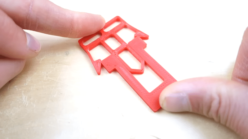
this is just about what i was thinking when i looked at it! and you can tell both from the photos of it in deformed extension, and from the photos of one of the failures, that the fillet is mechanically suboptimal. i don’t have a great approach to recommend but if you see that the flex of your part is focused at a single point instead of spread along the thin flexor arm, then you have room for improvement. off the top of my head, i think if it was slightly thicker at the base then it would not focus so much of the bending there. probably the thickness of the flexor arm should be some sort of decreasing function with the distance from its pivot point.
it’s great that you can specify these arbitrary shapes and just prototype it yourself in a couple hours but it’s also kind of a misleading power. a mechanical engineer can tell you the ideal shape of a flexor arm to distribute the flex over the length of it, but 3d printing isn’t exactly uniform, because the slicer has to build the shape out of several passes of a printing head. so depending on the choices of your slicer, there can be more going on than simply varying the thickness of the material. a thicker spot may be weaker in some sense because the print path may have a funny shape in it instead of nice long strokes across the whole work.
I’m actually not convinced that the fillet is suboptimal, most of the rest of design is! The arm does flex reasonably evenly and fillet or not that’s always going to be the point that takes the most bending force in this design and hence most stress without tapering the arm. I think the biggest problem (among many) is the big square head he’s trying to ram in. By the time the arms have opened wide enough for the mating peice to fit almost all of the forced being exerted is going directly down into the arm and not pushing it apart to slide past. Simply adding a 45 degree angle to the edges of the mating piece would make a huge difference to this. Hopefully this makes sense, a diagram would really help me out describing what I’m on about.
How can you relate percent elongation to bend angle?
If you assume a perfect arc with tangent ends, it’s a simple ratio of arc lengths. For example, for a nominally 40mm long part when straight, if we assume that 40mm (L) remains constant in the middle of the piece, as we bend it. Let’s bend it phi radians. The radius equals L/phi for that center. If this thing that’s bending has a th’k of 2mm (let’s call it W), we can project radially outwards, and get r_o = L/phi + W/2. We can turn these back into arc lengths as L_o = 2*pi*r_o. So if we’re interested in elongation. L_o/L = 2*pi*r_o/L = 2*pi*(L/phi + W/2)/L.
The whole videos could be replaced by a single sentence. Printing it in the right orientation.
And the channel name is only two letters out, should really be “Engineers groan”