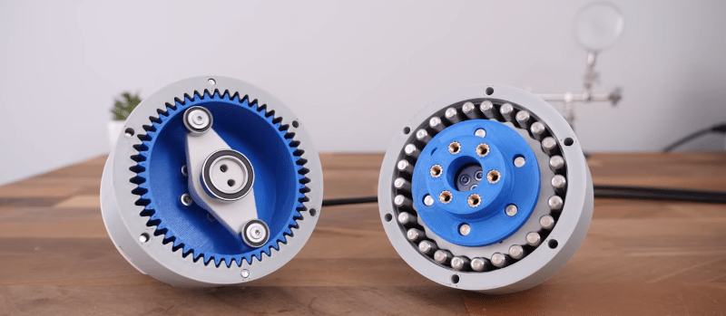
What’s better? Harmonic or cycloidal drive? We aren’t sure, but we know who to ask. [How To Mechatronics] 3D printed both kinds of gearboxes and ran them through several tests. You can see the video of the testing below.
The two gearboxes are the same size, and both have a 25:1 reduction ratio. The design uses the relatively cheap maker version of SolidWorks. Watching the software process is interesting, too. But the real meat of the video is the testing of the two designs.
You can also download the models yourself if you want to try your own testing. The blog post is “under construction,” but you can see some of the testing in the video. For example, the drives did show differences in backlash and torque testing. He also looked at some of the wear on key parts during failures.
Both of these drives look great, and depending on your needs, you might prefer one to another. But we always love these head-to-head tests. It makes it easier to do a trade-off analysis for your next design.
We’ve seen [How To Mechatronics] explain drive mechanisms before. If you think a 3D-printed gearbox can’t build up a lot of torque, you’d be wrong.


Excellent !!
tl;dw what’s the conclusion?
The cycloidal, because it’s a much bigger pain to build one :)
@Andrew said: “tl;dw what’s the conclusion?”
Go to 19:56…
https://www.youtube.com/watch?v=IXmCze1GsGU&t=1196s
To be fair, it’s not that the rest of the video is a waste of time – far from it, it’s worth watching all of it to fully understand what is going on. But the irrelevant ads periodically interrupting are at best obnoxious, so enable whatever still works to block them.
Didn’t watch because I prefer to read, not watch. What’s the conclusion?
3d printed gearboxes are waste of time.
But cycloidal will outlast and outperform harmonic one.
Isn’t quite true. 3D printed gearboxes are not a waste of time, they work well enough for most uses. If you needed anything for high loads or wear you should still use more traditionally manufactured gears. You find plastic gears in all kind of devices so why would 3D printed ones be a waste of time?
lol my az-el rotator holding a 1M dish driven by two NEMA 23 and cycloidal drives says otherwise .
one of my best projects from 2020. what a year.
PLA seems a less than ideal material to print a harmonic flex spline, isn’t it one of the stiffest?
Double thumbs down for this video. It’s just another recapitulation of the basic methods without any decent testing of durability, backlasy usability. I had some hopes when I saw 2 groups of 3 bearings in the harmonic drive, but this was dismissed again quickly, and apparently because of his 3D printer (or design) has sloppy tolerances. Engaging more teeth is a good thing when related to wear, but a 3D printed flexible is likely to show a lot of fatigue because of all the stress riser points in the internal geometry.
About the only good thing about this video is the use of steel pins in the cycloidal drive. dissimilar materials is likely to reduce wear and friction and enhance durability. The round pins are also likely to rotate a bit while the cycloidal disks run over them which further reduces friction.
Make steel great again. Dont want this flexible stuff.
You don’t want the springs on your [car, bicycle seat, train, bus] to flex?
B^)
Sometimes I think you guys read my mind, I’ve just been experimenting with an Idea I had for an alternate use for these gearboxes. I’m using a cycloidal gearbox since you can print one smaller on FDM, got one down to 13/8″
diameter. Tinkercad has a “flower” primitive that lets you adjust number & length of petals, this is my cycloidal gear with some holes drilled in it. Using yellow filament, so it looks like Honeycomb cereal.
Using them as the pivot joint in a mount for a display, or GPS in the car, or for cameras. I really don’t care for the ones that come with the above examples, typically a ball joint you tighten with an allen wrench that doesn’t stay tight, or some thing that limits you to the notches they put in it, but they all have some thing you tighten up that doesn’t stay tight. They all suck. If you use one of these with a knob it’s perpetually adjustable as well as perpetually stable (21-1 is my ratio). Perfect for 3d printed parts, wear from friction isn’t an issue. A little over an inch is a reasonable scale for a cell phone or GPS mount. A larger test seems like it would support a 19″ monitor, though I haven’t tried yet.