We’re all familiar with getting feedback from a rotating shaft, for which we usually employ a potentiometer or encoder. But there’s another device that, while less well-known, has some advantages that just might make it worth figuring out how to include it in hobbyist projects: the synchro.
If you’ve never heard of a synchro, don’t feel bad; as [Glen Akins] explains, it’s an expensive bit of kit most commonly found in avionics gear. It’s in effect a set of coaxial transformers with a three-phase stator coil and a single-phase rotor. When excited by an AC reference voltage, the voltage induced on the rotor coil is proportional to the cosine of the angle between the rotor and stator. It seems simple enough, but the reality is that synchros present some interfacing challenges.
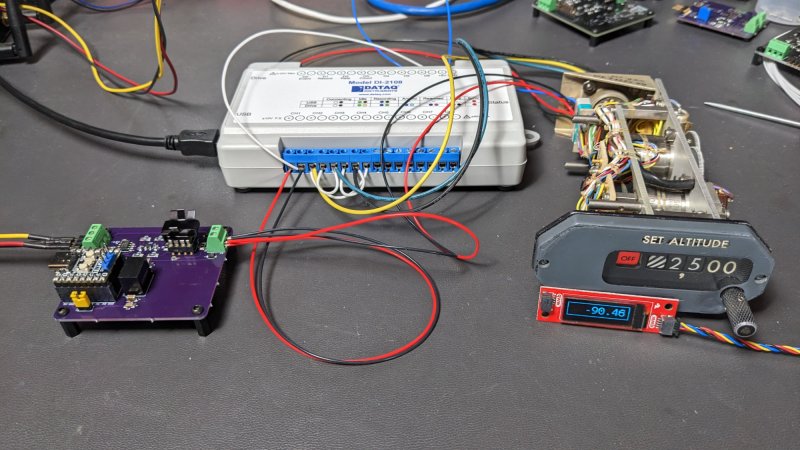
[Glen] chose a surplus altitude alert indicator for his experiments, a formidable-looking piece of avionics. Also formidable was the bench full of electronics needed to drive and decode the synchro inside it — a 26-volt 400-Hz AC reference voltage generator, an industrial data acquisition module to digitize the synchro output, and an ESP32 dev board with a little OLED display to show the results. And those are impressive; as seen in the video below, the whole setup is capable of detecting tenth-of-a-degree differences in rotation.
The blog post has a wealth of detail on using synchros, as does this Retrotechtacular piece from our own [Al Williams]. Are they practical for general hobbyist use? Probably not, but it’s still cool to see them put to use.


Absolute rotary encoders cannot also be avionic grade?
With synchros you get them locked together with a transmitter synchro and receiver synchro so there is nothing you need to do electronics wise to get them to synchronize to each other like you would with an absolute encoder and whatever you are using to display.
Two torque unit synchros coupled together will also provide you with force feedback, since the system works both ways. Turn either one and the other turns along.
you can also amplify the signal so you can control a big synchro with a little synchro. ac tech is freaking voodoo.
Synchros are 120 degrees. A similar device is a resolver, which is 90 degrees.
I’m curious about resolvers. I have a friend who did high radiation environment designs and it was all resolver based, and she thought they were great and a lot of fun to design with.
With no semiconductors inside them resolvers are immune to ionizing radiation. The only issue is you have to deal with driving them and reading them. There are modern resolver to quadrature ICs, I think Analog Devices still make them. They handle excitation and reading the resolver.
Also great for electrically noisy environments, the frequency of signal is indepenent of movement so you can put a really tight notch filter on and forget about the rest.
Most EV motors I’ve seen use a resolver for commutation, presumably for this reason. Imposssible to avoid interference when you’re stuck on the side of a honking great AC field coil, but pick an excitation frequency that’s far enough from the current motor frequency and you’re all good.
They also work underwater, full of oil, in bright sunlight etc and can handle higher vibration than many typed of optical encoder.
On the other side of the coin, making them truly linear is a challenge (and explains the cost) whereas an incremental encoder has to be made very badly indeed to be non-linear.
The big feature of synchros is that two can be directly linked, and the angle is transferred accurately between them. Very simple for remote control, as long as you have the needed AC voltage to drive them.
To read out the data digitally, fast ADCs are simplest nowadays. But further back, a rectifier, low-pass filter and DC measurement could have been a reasonable alternative.
I had some big synchros I bought surplus as a kid. They were rated 400Hz at 120V IIRC. I think it was power to each and 2 wires between them. I just use household power at 60Hz. They were fantastic. Whatever you did to one the other would track exactly. But it you gave one a spin with your fingers they both would slowly run away in a feedback delay to crazy RPM – I think from their angular momentum. The armatures were pretty heavy.
I am a great fan of resolvers. Both my CNC machines use them and on one occasion I swapped the encoder on a servo motor for a resolver for compatibility with the rest of the system.
It’s not that hard to read them, here is a simple circuit and some Arduino code that does it:
http://wiki.linuxcnc.org/cgi-bin/wiki.pl?ResolverToQuadratureConverter
A friend recently adapted this code for a project and found that square-wave excitation worked just fine, which simplifies things.
Note that as an analogue device it doesn’t matter what voltage you excite them with, so 3.3V from an Arduino is fine.
For a higher-resolution and/or more industrial solution there are other options. My CNC machines actually use: http://store.mesanet.com/index.php?route=product/product&product_id=101&search=7i49 (14 bit resolution) which keeps the absolute feedback aspect, and there is also https://pico-systems.com/resolver.html which uses one of the off-the-shelf resolver-to-quadrature chips.
It’s too bad these little buggers are hard to come by, they’re kind of fun to play with. Seems like with people building their own 3-phase brushless motors all the time these days, some enterprising soul should be able to create a synchro for cheap. Or somehow, idk, hack one from existing cheap motors.
Anyway, if you can scare up some old Data Device Corp (DDC) data books, there was a pretty good tutorial on synchro/resolver tec to be found in one of those.
Oh, fun fact – they’re great as long as you don’t try to push the speed too high. Of course, they were meant for linking control surfaces with gauges and or manual controls, where the system doesn’t even make a full rotation, or move very quickly. If you want the instantaneous angle of something that’s doing say 100 RPM, there’s an error factor for the speed, due to the devices acting partially as regular motor/generator hardware does.
Resolvers are routinely used for feedback and commutation on servo motors at 3000rpm or higher. Are you sure that this is a real problem?
If you dig into it, there’s a function that can correct the angle based on the speed.
curiousmarc’s latest YouTube offering explores a set of synchro/resolvers used in the Apollo command module,
A previous comment seems to have become lost in the aether. You can read resolvers with an Arduino, and square-wave excitation works just fine. As an analogue device they don’t care what the excitation voltage is.
Sample code and a circuit here (though using sine wave excitation): http://wiki.linuxcnc.org/cgi-bin/wiki.pl?ResolverToQuadratureConverter
Interesting idea…”grounding” one of the leads at half VCC and using a single-ended ADC to digitize the signal. I might have to try that with an RPi Pico. I have a two channel buffered op amp board. Use 1 channel to create a low-impedance “ground” at 1/2 the Pico’s ADC VREF (1.5 V) and the other to generate an ~6Vpp excitation signal that results in a 3Vpp output that’s within the Pico’s ADC input range. I’d prefer to stick to a tracking converter rather than sampling the signal at the peak and doing an instantaneous conversion though. The tracking converter has better noise immunity and is less sensitive to phase offsets between the reference signal and output signals.
We had them in 5″/54 caliber gun mounts. MK45 mod 0 and 1. The were used for positional feedback in gun training and elevation.
I picked up a WW2 era radio compass dial synchro years ago. I don’t have the sending end though. It would make a great antenna indicator. One trick I did was to put audio in the single phase winding and hook 2 of the 3 phases to stereo monitoring. Turning the shaft causes a Leslie effect in a complex way even sending the sound to the rear in a surround matrix setup, no Doppler effect though.
Anyone know a source for a pair of reasonably inexpensive synchros? I’ve done some searching and haven’t found any yet.
Ebay 403741608393 maybe?
Would Resolvers do? Or are you actually interested in the spooky action at a distance of paired synchros?
Try searching eBay for “Muirhead” and “Tamagawa” and you might find some bargains from people who don’t know what they are selling.
Yeah, I was interested in the action of a coupled pair to maybe use as a backup direction indicator for my rotating ham radio antennas. Thanks for the eBay link but I’ll probably go with something simpler since I don’t really need very high resolution. I think it’s crazy that some ham radio rotator displays read out to 0.1 degree when the beam pattern of the antenna is probably 40 degrees wide or worse at the 3 dB points.
We use synchros for marine steering systems we build, there’s a set in the rudder follower as well as in the lever controls in the wheelhouse. Used primarily in follow-up steering where you move the lever control to a specific degree & the system runs the hydrologic rams to match.
You may find them in old yacht instruments. A masthead wind vane at one end and a wind angle with pointer rotating over boat graphic display at the other.