Thermal cameras are great if you want to get an idea of what’s hot and what’s not. If you want to use a thermal camera for certain machine vision tasks, though, you generally need to do a geometric calibration to understand what the camera is seeing and correct for lens distortion. [Henry Zhang] has shared various methods of doing just that.
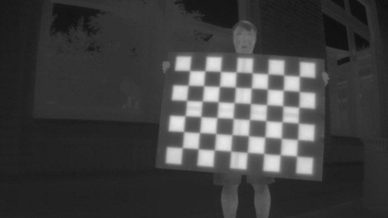
To calibrate a thermal camera, first you need a thermal pattern. This is like typical test image for a camera or screen, but with temperatures instead of colors. [Henry] explains several methods for doing this. One involves using a grid of nichrome wires to create a thermal pattern for calibration purposes. Another uses discs of cold aluminium inserted into a foam board. Even a simple checkerboard can work, with the black spaces heating up more from ambient sunlight than their neighbouring white spots. [Henry] then explains the mathematical techniques used for calibrating based on these patterns.
It’s a useful primer on the topic if you’re working with thermal camera systems. We’ve looked at some other interesting machine vision topics before, too. If you’ve got any great thermal imaging tips of your own, don’t hesitate to drop us a line!


Good ideas! We made a checkerboard target out of a powder coated aluminum plate and some metallic duct tape. The powder coat and shiny tape have very different emissivities so simply make the entire target hot and the pattern appears!
For a minute, I thought that was a picture of me. I did this for work in the summer of 2014 for an aerospace company.
Same, I use a clipboard with aluminum foil and plastic ziptie tiles. Then I heat the unit with a heat gun and the plastic stays warm and the aluminum is cold.
I did a similar thing and worked perfectly.
As clever as you think the setup of the article might be, they have read or use the camera to little not to know/notice it can differentiate objects at room temperature.
From the title I thought this was about calibrating thermal cameras with heated things. As in: calibrating the reported temperatures. But no, it’s textbook geometric calibration of an imaging system.
So: why do you need to go through the complexity of building a structure with different temperature components? Just use different materials with different emissivities.
The FLIR camera manual even has a helpful table in it to help you select materials. Alumin[i]um foil squares on a sheet of unfinished (or painted) plywood would work just fine. If you chose polished alum* you’d need to take a bit of care not to reflect hot objects into the camera though.
Before I clicked the link to Hackaday, that’s what I thought the article was going to be about. Different emissivity to see the grid.
Thanks for all the nice ideas!
My way of intrinsically calibrating a thermal camera:
I was using a heated oven plate as heatsource (everyone should have one). Then i fixed a printed chessboard to a wood plate covering the oven plate and drilled holes into the chesspad intersections of the grid. The drilled holes are observable by the thermal sensor as the oven plate is shining through it, by using the
The detected points can be feeded directly into opencvs cv.calibrateCamera() function to get the intrinsic calibration.
Here is the code to run the actual calibration:
https://gist.github.com/julled/ed1934f059417f742838bded8988f46b