Remember fax machines? They used to be all the rage, and to be honest it was pretty cool to be able to send images back and forth over telephone lines. By the early 2000s, pretty much everyone had some kind of fax capability, whether thanks to a dedicated fax machine, a fax modem, or an all-in-one printer. But then along came the smartphone that allowed you to snap a picture of a document and send it by email or text, and along with the decrease in landline subscriptions, facsimile has pretty much become a technological dead end.
But long before fax machines became commonplace, there was a period during which sending images by wire was a very big deal indeed. So much so that General Motors produced “Spot News,” a short film to demonstrate how newspapers leveraged telephone technology to send photographs from the field. The film is very much of the “March of Progress” genre, and seems to be something that would have been included along with the newsreels and Looney Tunes between the double feature films. It shows a fictional newsroom in The Big City, where a cub reporter gets a hot tip about an airplane stunt about to be attempted out in the sticks. The editor doesn’t want to miss out on a scoop, so he sends a photographer and a reporter to the remote location to cover the stunt, along with a technology-packed photographic field car.
After the “snapper” gets some shots of the stunt by hanging onto the roof of the van, which honestly seems more dangerous than what the pilot is attempting, the real fun begins. He passes the exposed film into the photo lab section of the van, where a darkroom tech processes the film using what appears to be the standard wet process. How exactly this is accomplished while the van is speeding toward the nearest telephone pole isn’t detailed; some things you just have to take on faith.
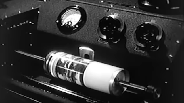
Once the van reaches a telephone pole, they need to connect the van to the telephone network. After donning pole-climbing gaffs and period-correct PPE — a fedora — the reporter climbs the pole to make the connection. The old “press card in the hat band” trick used to buy you a lot of leeway, we suppose. Inside the van, the now-developed photograph is wrapped around the drum of a scanning machine, which aims a narrow beam of light onto the black-and-white image. Reflected light is picked up by a phototube, which translates it into an audio tone that goes straight into the earpiece of a wonderfully retro candlestick phone. Back at the newspaper, a receiver translates the audio tones into varying brightness on a neon bulb, which exposes a sheet of photographic film wrapped around an identical drum to reproduce the image in minutes.
The genius bit about this setup is its completely analog nature. As long as the sending and receiving drums are the same size and rotating at the same speed, there’s no need for any kind of synchronization signals or handshaking. And the fact that the output of the receiver was ready to rush down to the press room in time for the evening edition must have been a boon to the editors.
But really, the gem of this piece was the visualization of the facsimile process using two rolls of string, and how an image could be serialized and deserialized. Encoding a message on a string wrapped around a drum and then randomizing the string by balling it up seems like a low-tech way to exfiltrate information under hostile conditions, as long as your recipient knows what size drum to use for decoding. There’s your Hackaday fieldcraft lesson for the day.
Thanks to [Mike Bradley] and [Keith Olson] for the tip.


> Encoding a message on a string wrapped around a drum and then randomizing the string by balling it up seems like a low-tech way to exfiltrate information under hostile conditions, as long as your recipient knows what size drum to use for decoding.
The Scytale cipher!
Cool! I remember seeing one of these machines as a kid around 1960. I thought it was pretty amazing then, and for that matter, it still is.
The Hellschreiber is a similar technique, that used very simple hardware for transmitting text and even pictures. It’s still being used by amateur radio operators for transmitting information (and for fun).
Here’s a short demo video about Hellschreiber, btw. Including the AF signal on the scope.
https://www.youtube.com/watch?v=l2zLL0Z-zI4
Of course, there are modern applications for Hellschreiber, too.
How would you keep the drums in sync, though? Even a very small discrepancy would cause distortion of the resulting image. Consider how difficult it is even today to keep vinyl turntables rotating a the correct speed.
That drum looked like it was rotating about once a second; if we assume a square image of 200 lines, that’s 200 seconds. A 0.1% speed difference would be a cumulative distortion of 0.2 lines or the equivalent of 40 pixels (if the picture used pixels, which it doesn’t). Realistically you’d need 0.01% accuracy for a distortion of 4 pixels. How would you do that with the technology of the day? Assuming I got the maths right, of course.
Mains frequency synchronized (Although I am not sure whether there was one big mains frequency locked grid in the 1930’s)
US mains was synchronized for the first time in 1978, in Europe full synchro happened only in 2011. It took several years for ex-soviet nations to replace their turbogenerators and transformers before they became compliant with EU grid.
Each end probably just used the local 60Hz mains frequency to establish the proper rotational speed. No need for separate grids to be synchronized. It probably did involve some tinkering and adjustment if one end was a little off.
I might be getting my mental model wrong but a mismatch would lead to the photo being stretched.
This would be relatively easy to fix if needed when the photograph was reviewed (you could probably tell from the distance between the edges of the photograph if nothing else).
If you’re imagining that the photograph was a perfect fit around the drum edge to edge then that would be a problem as it would cause slippage I believe.
It would lead to the photo being skewed (formed into a parallelogram). Nothing a competent photo editor (in a darkroom of the ages) couldn’t fix. A mismatch over time of transmission would be more of a problem.
Send a sync signal along with the image. The horizontal clip holding the photo to the drum would be handy for generating one.
Yes that’s exactly how it works. Vertical and horizontal syncs are based on a black band at the top and on the left or right side.
The holding bracket probably helps in alignment and syncing of the system after the fact. It would make sense that after development, they can measure how off the sync is directly from any slant in the picture’s edges and call the sender with the correction info to try again.
From the description of the system in the video, it probably used a tone wheel on the sending drum to generate a sync signal, and modulated the amplitude of the tone to send the picture. After all, to get through the phone network, you need an AC signal somewhere between 300 – 3000 Hz. You can’t just send a DC current down the line.
Or, they sent two tones. One for synchronization and another at a different frequency for the picture.
The small town newspaper I worked at in the 60s and 70s had an AP Wirephoto machine. I picked one up at a garage sale circa 2000 but had to discard to move. An explanation is shown at https://apimagesblog.com/historical/2019/12/12/85-years-of-wirephoto My recollection is a metal drum over which a mimeograph type paper is installed. An electric stylus would discharge to mark or expose the paper. The sending photocell output was modulated with a carrier wave that also synchronized the sending and receiving drum rotation.
Since this was coming from a mobile unit (assuming the only utility tap was the telephone without mains reference and the demo animation shows a bettery) I would say it’s just a calibrated clockwork mechanism
I have no idea what they used here, but a teletype does it by halting the drum on each rotation, and releasing it when it receives the start pulse: it does a single rotation and stops, slipping on the clutch until the next start pulse comes along. Such a mechanism can tolerate a difference of 10% or more in timebase between transmitter and receiver.
Teletypes were pretty common technology around then, it seems reasonable to assume they’d use the same mechanism here. Especially since the transmitter did not necessarily have a 60 Hz line to power it, if the film is to be believed.
In addition to start/stop syncing, teletype motor speeds had to be closely matched. In standard landline machines this was done by using line-synchronous motors. But in mobile military RTTY systems, power lines were not available for syncing. Special Kleinschmidt machines were used. A variable speed motor with a strobe disc was measured with a tuning fork that had an optical shutter to view the disc. The speed was adjusted til the disc appeared to stand still.
The analogue fax systems like WEFAX (used for distribution of weather charts) and APT (used by NOAA satellites) do have sync pulses in the analogue signal.
If they start out with a kind of metronome or sync tone and a continuously variable clutch on the receiving end, I think it shouldn’t be too difficult to get close enough just by ear and eye. If there’s still some error left a photo editor could fix it, or maybe the low quality of the printed result would mask it?
Or maybe there was some carrier tone on the phone lines, I don’t know about that.
My late dad was in the Philippines in WWII. Besides being a soldier in the trenches he was a photographer for the United Press Service (I think it was called). This is how he sent photos back to the states via an optical scanner transmitter. I still have his Speed Graphlex 4×5 and his album of pics including shots of the signing of surrender and the devastation of the war on the islands.
As a kid I remember my Dad’s box of stuff from the Second World War. In there was a letter he had written to his mother in the early 1940s from Egypt or Libya (Tripolitania then) and sent by radio to London, printed on very thin blueprint style (photosensitive?) paper. This was apparently a similar system to the above. There certainly wasn’t any chance of the mains in North Africa being in sync with wartime London’s mains, so I guess a sync signal was transmitted along with the analogue data. I don’t remember any artefacts apart from a slight banding, but it was very recognisably my father’s handwriting. Later in life when I read about this new fangled “fax” I realised it was basically the same system updated, then remembered that my dad’s letter was labelled “Facsimile transmission”.
I wonder if this document would be considered an example or variation of what was referred to as “Victory Mail” created during World War II. See below:
” Although the V-mail system was only used between June 1942 and November 1945, over 1 billion items were processed through these means. Officially entitled the “Army Micro Photographic Mail Service,” War Department Pamphlet No. 21-1 describes V-mail as “an expeditious mail program which provides for quick mail service to and from soldiers overseas. A special form is used which permits the letter to be photographed in microfilm. The small film is transported and then reproduced and delivered. Use of V-mail is urged because it greatly furthers the war effort by saving shipping and airplane space.”
And it avoids losing important mail if the ship sinks.
A wind up clock mechanism is accurate enough
QST had an article about FAX, May 1972 on page 23. The machines were showing up in surplus, for as little as $20. There’s a schematic and maybe more details.
I had one if these machines and the aforementioned QST article, which included details on the mods necessary to make it work on radio. IIRC, the image was synced by a sync pulse st the start of each drum rotation.
My buddy and I each had one, and we were gonna put ’em on the air, but we both wound up moving, and the machines went the way of all things.
I (we) saw something similarly reproduced on The Secret Life of Machines tv show. Trying to synch up the speed of two lathes to do a similar effect.
Yes the fax machine episode
It would be so shockingly easy to make one of these today, it really makes me want to try.
That demo with the string and the image of the car really sells it!
Up the challenge: make it work on a string-on-can telephone, purely mechanically.
Or, even using the same method used in the video with a nylon fishing line spooled over a drum, traveling between two houses. You could use erasable whiteboard markers and rub the picture off of the wire onto a piece of paper once received.
By the 30’s this stuff was as old as the hills, here’s a link to a Wikipedia article of a technology from the 1860’s.
https://en.wikipedia.org/wiki/Pantelegraph
Yes, but unlike the 1907’s belinograph this does not transmit pictures, only hand drawings.
The Kenwood IP-100 Illustphone does exactly that. You draw on a small area and it transmits the pictures (in color!) as audio tones. It can decode and print them too using small color styluses (one color at a time and you have to change it by hand). I have 4 (or maybe 6?) IP-100’s and will bring a couple at MakerFaire ham’s booth if they ever have it again in the Bay Area some day.
I’m not in the Bay area but I am going to google the Kenwood IP-100 Illustphone.
Well, that’s a pretty neat trick, sending sound into the EARPIECE!
So I checked the film and, sure enough, that’s what they did.
Rigged demo, acted by someone who didn’t know an earpiece from a microphone.
Though, same is true even today, seeing most folks who walk down the street yelling into their phones held in front of their faces.
And, sure enough, that’s the way it is supposed to work. If it were intended to be used with the transmitter (the horn on the candlestick telephone) then the acoustic coupler would be made to fit over the mouthpiece. As it is, the earpiece clearly sits on a pad with a speaker in it – the pad is clearly made to fit the earpiece.
In a simple telephone circuit, the speaker and microphone are essentially in parallel across the phone line. A speaker can be used as a microphone, no problem. There may be some difficulties with the signal level, but there’s no reason why it wouldn’t work.
There’s no hybrid transformer in a simple candlestick telephone:
http://www.samhallas.co.uk/collection/bits_candle_3.htm
The diagram in that link shows the transmitter (microphone) and receiver (speaker) NOT connected in parallel, but instead connected via separate T and R lines to the counterwound transformer in the bell set, where the line terminates. That does look an awful lot like a hybrid.
Those receivers were just a metal plate over an electromagnet. Though biased by a permanent magnet, they still made really awful microphones.
I wonder if the coupling was electromagnetic, skipping the sound transduction part entirely: just a coil in the pad coupling to the coil in the receiver. That would actually make sense.
Indeed the transformer, referred to in “telephonese” as an induction coil, was a true hybrid, as described in Bell System literature. (The “practices”, or “BSPs”). The more modern receivers, such as was used in type 500 and later sets, was a moving-coil device, like a modern speaker or microphone, and i have used them with excellent results as dynamic mics in 2-way radios.
Inductive coupling into the winding of the receiver does indeed work, and is the method of choice for use with hearing aids. In fact, the FCC requires that the magnetic field of the receiver coil be made available for hearing aid use. It would certainly also work for transmitting, since the circuits in the older phones were passive and would pass signals in either direction.
Talking into the receiver of a standard electronic does work, as i have confirmed by experiment, as a sound powered phone, tho of course the signal level is lower. This is less of a problem in tone signalling than in voice communication. And candlestick phones do have hybrids, in the separate box that contains the ringer.
Some words got left of my previous reply: instead of “standard electronic” i meant “standard non-electronic telephone” such as the Western Electric 500/2500 Sets, aka “Bell System” phones, which circuits were totally passive in nature.
If I recall correctly, telephones of that era used a carbon microphone. Carbon microphones work as pressure-sensitive variable resistors, and don’t work without a DC supply. They are properly considered active devices because they provide gain.
So, carbon capsule microphones are active devices, like potentiometers, load cells, CdS light sensors, and thermistors?
That technology is still in use.
Weather FAX (WEFAX) uses the same principle.
The German weather service, DWD, provides daily transmissions on shortwave.
One is at 3853,1 KHz USB (DDH3 station) in the 80m amateur band.
Sample video w/ vintage equipment: https://www.youtube.com/watch?v=vIh1RwrI4hs
Video w/ Macintosh: https://www.youtube.com/watch?v=iWVsgMLnE54
Yes and US Coast Guard still send weather charts on HF today. South-East Asia and China also do daily.
Another cool one is Kyodo News Agency which sends japanese newspapers pages that exact same principle over HF radio. A few WebSDR’s do have the APT and radiofax plugin and allow to receive and decode that in a web browser.
It takes several long minutes to get a page printed out line by line but is definitely worth the wait when the conditions are good (less noise and fading).
Cool, thanks a lot for the infomstion! 😎👍
What always fascinated me was the high-res nature of fax.
That’s what motivated me to get a used PK-232 multimode TNC years ago.
Sure, it’s black and white only*, but it’s somewhat efficient and simple considering the low bandwidth it uses (~2-3 KHz).
Back in the last century, I assume, radio fax was very useful to share technical schematics over amateur radio or something along these ‘lines’ (pun intended).
In a similar way, the low-res 8s SSTV was useful. It could be used within normal conversations, to share a picture.
(*There technically was grayscale and colour fax, but it never got popular)
This article fails to mention that this was invented 30 years before by Édouard Belin. Édouard Belin developed the belinograph in France in 1907, i.e. 30 years before Ford’s Spot News demo, and started filing patents in 1913. The belinograph scanned pictures on a drum using a photocell and thus enabled photographs to be transmitted and converted on the receiving end to halftone photographic images using light to expose photographic paper on an identical drum. Earlier attempts such as the telediagraph did not transmit pictures.
The belinograph ultimately formed the basis for the Associated Press, and images transmitted in this manner were referred to as “belinos.” Images could be transmitted over standard telephone lines. Western Union began transmitting halftone photographs in 1921, ATT in 1924, and RCA in 1926.
How come this fact was completely absent from this article’s introduction paragraph? And that this happened 30 years before Ford’s 1937’s Spot News demonstration?
A similar mechanism was/is used to transmit analog weather satellite pictures (aka WEFAX in APT format). The first satellites that transmitted these pictures actually rotated at 120 RPM to scan one line of a section of earth and clouds underneath per rotation. Those signals are still transmitted today by a number of weather sats around 137 MHz. Newer sats use digital encoding and higher frequency bands for clearer pictures.
Such a line-by-line mechanism is still in use today to transmit full pages of newspapers in Japan over HF bands (see JCC Kyodo News Radiofax) and is quite slow but works. Several WebSDRs have plugins to automatically decode radiofax and display those pictures in a web browser.
This is also in use by USCG and other countries coastal services to transmit weather charts and occasionally other news over HF. Mariners and fishing boats still use that today and print the images on a regular thermal printer (which actually also has a drum but the lines are not printed one at a time).
A faster but similar technique is SSTV (slow scan TV) and is used on ham radio bands (HF) to transmit analog pictures over long distances. The ISS ham’s aboard in the crew regularly send SSTV picts that way also on ham radio bands.
An even faster but identical technique was used to transmit pictures from the first landing and first walk on the moon but I forgot how it was called.
“standard wet process. How exactly this is accomplished while the van is speeding toward the nearest telephone pole isn’t detailed; some things you just have to take on faith.”
That’s not a problem if you have a developing tank with a lid.
For roll film there were even easier contraptions:
https://photo.stackexchange.com/questions/109101/how-was-film-developed-in-the-late-1920s
To make wet field processing even simpler, there were single bath developers that contained the developer and fixer in one solution. I remember reading about at least one case where the photog processed his films in the seat of an airliner, in flight. Ah, the good old days.
The prints from most such processes were called “stabilized” and had poor lifespan, fading to white or gray or tan after weeks or months or years. Rinsing out the residual chemicals (preferably after first re-fixing) could produce a stable product.
I believe that the recon version of the B-36 bomber had something like this. The plane carried a camera with a huge lens; each photographic negative was the size of an open large newspaper (like 2 pages of the NY Times); the plane carried a load of ‘flashbombs” to aid in taking photos; and the plane also had a darkroom inside so that the negatives could be developed onboard while the aircraft was returning to base. Upon landing, analysis of these huge aerial recon photos could begin almost immediately.