When building autonomous airborne vehicles like drones or UAVs, saving a little bit of weight goes a long way, literally. Every gram saved means less energy needed to keep the aircraft aloft and ultimately more time in the air, but unmanned vehicles often need to compromise some on weight in order to carry increased computing abilities. Thankfully this one carries a dizzying quantity of computer power for an absolute minimum of weight, and has some clever design considerations to improve its performance as well.
The advantage of this board compared to other similar offerings is that it is built to host a Raspberry Pi Compute Module 4, while the rest of the flight controllers are separated out onto a single circuit board. This means that the Pi is completely sandboxed from the flight control code, freeing up computing power on the Pi and allowing it to run a UAV-specific OS like OpenHD or RubyFPV. These have a number of valuable tools available for unmanned flight, such as setting up a long range telemetry and camera links. The system itself supports dual HD camera input as well as additional support for other USB devices, and also includes an electronic speed controller mezzanine which has support for quadcopters and fixed wing crafts.
Separating non-critical tasks like cameras and telemetry from the more important flight controls has a number of benefits as well, including improved reliability and simpler software and program design. And with a weight of only 30 grams, it won’t take too much cargo space on most UAVs. While the flight computer is fairly capable of controlling various autonomous aircraft, whether it’s a multi-rotor like a quadcopter or a fixed wing device, you might need a little more computing power if you want to build something more complicated.


Wow! This is an impressive piece of work. I’ve had a similar idea tossing around in the back of my head for a while, but now I’m glad I didn’t pursue it yet because they’ve done it so much better!
Of course the design seems well documented but doesn’t actually appear to be open source, so perhaps that’s a miss…….
Thanks!
It’s currently not open source to avoid clones however I do try to publish as much information as possible, short of releasing the full schematics! I’m always happy to add more information to the wiki if there’s requests for it!
What’s the point in trying to save weight, then choosing a Raspberry Pi Compute Module 4 (CM4)? The added batteries needed to feed the power-hungry CM4 module weigh a lot to begin with! Then there is the issue of even finding a CM4 much less being able to afford it, unless you have been selected as one of the Raspberry Pi Elite customers. Start over again and concentrate on energy efficiency first.
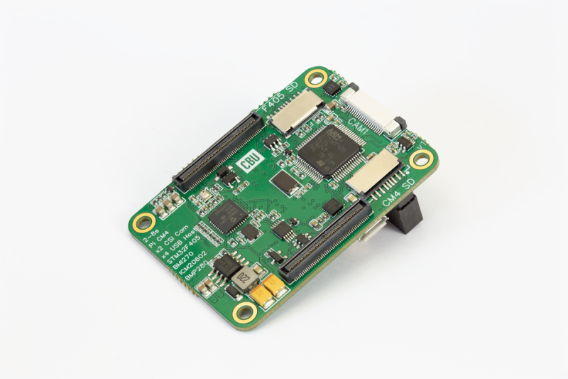
Also, choose a SoC you can actually src and buy yourself, so you can customize your own PCBA, optimized for weight. I don’t know exactly what a CM4 is but I guess it’s a plugin module to the large & heavy dimm-connector in the picture. That’s a lot of dead weight right there and a hard constraint on how small you can make your board to begin with.
That said, still kudos for actually doing the project at all. It’s easy to complain & have opinions on other people’s work, but granted I’ve not put in any of it myself…
So yeah, cool project. And nice to still have room for future improvements ;) – just not with the RPi SoCs, since (afaik) you actually can’t src them to put in your own DIY designs ?
Alright wise guy, what other SOM would you suggest that puts more computational horsepower in less weight? Lazy troll is lazy, but in case you’re actually not trolling and just astoudingly ignorant, I’d like you to show us all your superior sourcing choices and prove otherwise.
@Myself said: “Alright wise guy, what other SOM would you suggest that puts more computational horsepower in less weight? Lazy troll is lazy, but in case you’re actually not trolling and just astou[n]dingly ignorant, I’d like you to show us all your superior sourcing choices and prove otherwise.”
Sheesh, someone got up on the wrong side of the bed today :-(
Off the top of my head I think two interesting devices are relatively small, fairly inexpensive, readily obtained, and should provide a path to multitasking in a UAV application. One approach uses speed which would work well with a RTOS. The other approach uses multiple processors commutating through an on-chip hub. I have used both of these devices quite a bit. It is surprising how much can be accomplished with the Propeller-I multi-core part, especially when programming in assembler and/or C++.
1. Teeny 4.0, ARM Cortex-M7 at 600 MHz, $23.80 per module
https://www.pjrc.com/store/teensy40.html
2. Parallax Propeller-I, 8 x 32-bit commutating cores (cogs), $11.19 per 40-PDIP chip
https://www.parallax.com/product/propeller-1-chip-40-pin-dip-chip/
You can think of the Flight controller as 2 separate systems;
There is a STM32F405 (Cortex M4) which runs ArduPilot using a real time system (Chibi OS). This interfaces all the sensors, calculates the motor outputs and actually flies the aircraft. It is embedded on the main PCB. There are other ICs that are compatible with ArduPilot I could use instead, and there are plans for a STM32H743 version (Cortex M7) in the future.
The Raspberry Pi Compute Module is a “System on Module” that runs Linux natively, NOT in real time. It attaches to the PCB using x2 Hirose 100 pin connectors and acts as a “companion computer”. There are a variety of SOMs but the Raspberry Pi is most commonly used, already has great support and faces the same stock challenges as other SOM manufacturers. It is also incredibly powerful-64 bit, 8gb ram, quad-core ARM Cortex-A72 @ 1.5GHz.
The Pi can talk to the STM32 and pull/push aircraft telemetry directly from the control loop, giving access to things like; location, attitude, battery life etc in a normal python environment. The advantage here is that any Pi compatible sensor can be utilised for external aircraft control.
For example, Pi Camera > Pi Compute Module (Python script for face recognition > Python Send Attitude Command) > STM32 (Control Loop points toward python target). Less than 30 lines of code in a familiar programming language on a well documented bit of hardware!
I’m never very good at doing these things justice but I would recommend checking out https://ardupilot.org/dev/docs/companion-computers.html for more information on the use of Companion Computing
The Compute Module (11g) was chosen as an alternative the the full size pi’s (46g) which would normally be used. They are about 25% the weight and 66% the size.
Power consumption wise, once booted the whole system (Flight Controller/GPS/CM4 etc) uses roughly 2.94 W, increasing to 4.2 W if both cameras are streaming). Compare this to an example 100g AUW build where all the motors can pull 100 W to hover, the impact of the CM4 is minimal on battery life. This flight controller is also very happy flying larger aircraft where the difference is even less; a 7kg AUW might use 1,400 W to hover!
That is very true, and we faced the same recently but there is good news! A recent commercial agreement with the Pi Foundation means that we will be able to offer (and have in stock) CM4’s at RETAIL price available for purchase alongside the Flight Controller, hopefully within a month!
That’s amazing. I’ve never seen a Pi run on less than 10W. Anything less than 5v 2A and I can’t get the darn things to boot.
How do you get power draw so low?
I should state that’s input current, 0.4A at 8.4v, not output current from the 5v regulator. The Compute module is surprisingly efficient depending on accessories. It is still wise to have a lot of overhead available, as during boot it can spike up to 0.8A but settles once booted to about half that.
I dont bother with lifters much anymore but during covid that was my hobby. I have seen at least two examples that can lift their own power supply and wondered about using a flexirigid circuit board to reduce weight. Has anyone else considered this for simikar flying robots?
I dont fully understand what you mean by lift there own power supply, do you mean running off mains electricity with an inverter on the drone to remove the battery? Its certainly possible!
Flex PCB would be an interesting progression and is likely what the Black Hornet is using.