When working on simple DC systems, a small low-cost multimeter from the hardware store will get the job done well enough. Often they have the capability for measuring AC, but this is where cheap meters can get tripped up. Unless the waveform is a perfect sinusoid at a specific frequency, their simple algorithms won’t be able to give accurate readings like a high-quality meter will. [hesam.moshiri] took this as a design challenge, though, and built an AC multimeter to take into account some of the edge cases that come up when working with AC circuits, especially when dealing with inductive loads.
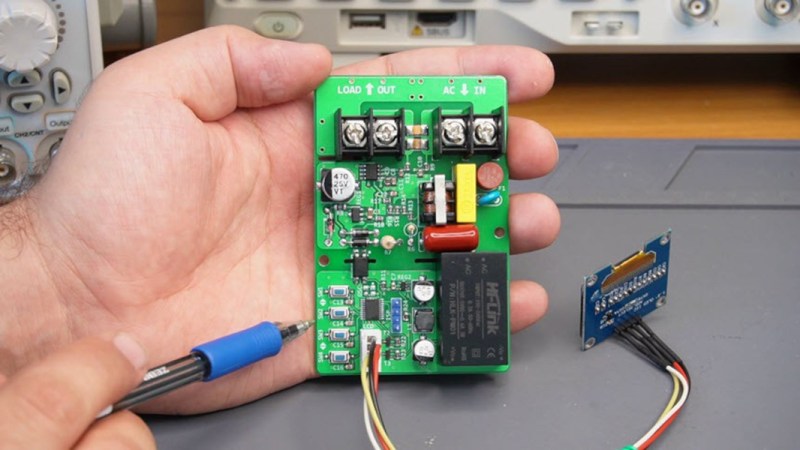
The small meter, an upgrade from a previous Arduino version that is now based on the ESP32, is capable of assessing root mean square (RMS) voltage, RMS current, active power, power factor, and energy consumption after first being calibrated using the included push buttons. Readings are given via a small OLED screen and have an accuracy rate of 0.5% or better. The board also includes modern design considerations such as galvanic isolation between the measurement side of the meter and the user interface side, each with its own isolated power supply. The schematics and bill-of-materials are also available for anyone looking to recreate or build on this design.
With the project built on an easily-accessible platform like the ESP32, it would be possible to use this as a base to measure other types of signals as well. Square and triangle waves, as well as signals with a large amount of harmonics or with varying frequencies, all need different measurement techniques in order to get accurate readings. Take a look at this classic multimeter to see what that entails.


the actual (not that detailed) article is here https://www.pcbway.com/blog/technology/Digital_AC_Energy_Measurement_Circuit_V2_RMS_Voltage_RMS_Current_Real_Power_P_a1bf4da8.html
No details on how it does anything, no firmware source code, and no esp32 in the circuit diagram (it uses a STM32).
So I’m wondering why it is in the HaD prize group…
“The schematics and bill-of-materials are also available for anyone looking”
Where? No link visible.
The youtube video has two links in it’s description. One to the altium website, and another to pcbway:
https://www.pcbway.com/blog/technology/Digital_AC_Energy_Measurement_Circuit_V2_RMS_Voltage_RMS_Current_Real_Power_P_a1bf4da8.html
Apparently it uses an HLW8032 which does all the measurement, and it seems to push serial UART data through the isolation barrier (opto coupler).
Yet another project which is the same as all those others before it. I’m more interested in accurate low power measurement. Such as measuring standby current / power of stuff in the sub milli watt range. I guess it’s not too difficult to do but you will need a switchable shunt resistor for measuring the low current. I may add this to a project like this some day, but at the moment I’ve got more projects in my head then I can manage.
In case my other comment doesn’t get past the filter.
Check the hackaday io page for this project. There’s a link that seems to lead to the project site and embedded link to the sales link for parts.
project/193066-digital-ac-energy-measurement-circuit-pro
What ESP32? This board uses an STM32 microcontroller…
I tried this comment before, and it wouldn’t post –
the actual (not that detailed) article is here – LINK REMOVED TO SEE IF COMMENT WILL POST!
No details on how it does anything, no firmware source code, and no esp32 in the circuit diagram (it uses a STM32).
So I’m wondering why it is in the HaD prize group…
yep, wouldn’t post with the link to the full article..
so, an hard to believe, the comment system at HaD has got worse…
Nice separation between low and high voltage side, except those push buttons, whic are eerily close for ppl with phst fingers.
lol “modern design considerations such as galvanic isolation”.
Thanks for making me feel young again… it was already a design consideration long ago… luckily… :)
Seems like a lot of trouble to go to, since Analog Devices has been making low-cost, single-chip RMS-to-DC converters (the AD 536/636/736 series, among others) for an awfully long time. So long, in fact, that there’s a wealth of information available in the form of application notes and design articles, such as the following–
“AD536AIntegrated Circuit,True RMS-to-DC Converter”
https://www.cs.cmu.edu/~RAS/old/DataSheets/ad536a.pdf
“New Products Appendix to the RMSto DC Conversion Application Guide”
https://www.analog.com/media/en/training-seminars/design-handbooks/rms-dc-app-guide-appendD.pdf
“Designing a True RMS to DC Converter using IC AD736”
Published February 28, 2020
https://circuitdigest.com/tutorial/true-rms-to-dc-converter-using-ad736-ic
“Understand How to Effectively Monitor Signal Voltage and Power with RMS-to-DC Converters”
By Art Pini
Contributed By DigiKey’s North American Editors
2018-09-25
***EDIT***
The last reference should have included a hyperlink; here ’tis–
“Understand How to Effectively Monitor Signal Voltage and Power with RMS-to-DC Converters”
By Art Pini
Contributed By DigiKey’s North American Editors
2018-09-25
https://www.digikey.com/en/articles/understand-how-to-effectively-monitor-signal-voltage-and-power
Those chips do look interesting..
And how did you get a comment to have a link anyway? Every time I try it won’t post..
“…And how did you get a comment to have a link anyway?…”
Very sophisticated answer: pure dumb luck.
Even though HAD doesn’t have a “preview” function, one day I decided to try and type in, or paste, the URL (BY ITSELF, on a completely separate line; see the entry/entries above)–and it worked!
I haven’t tried the HTML-tag redirection trick, “<a href=…" here on HAD (may not work, anyway), but as long as simply typing the URL works, that’s good enough for me…and a lot easier than trying to remember the syntax of the HTML
"<a href..."tag.Best of luck.
I’m not sure if it still works this way, but a URL without any other text would not post to Comments (anti-spam feature? )
I also text a line before the URL .
Another Hackaday.io post with NO REAL INFORMATION! Where is the schematic and BOM? Missing again. There’s just some person on YouTube holding a PCB and talking on-and-on. Before some Hackaday.io article gets pointed to by a real Hackaday.com post, it should meet certain minimum standards: like a readable schematic and BOM in .pdf format.
You should not be hurry, Don’t you see the link on the left side down?!!!
another complaining comment:-))))