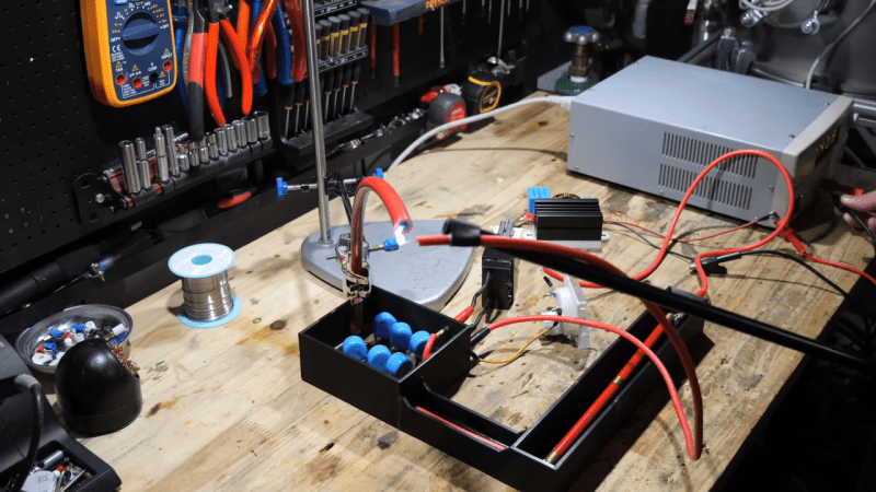
It’s not entirely clear why [Advanced Tinkering] needs a 50,000-volt power supply, but given the amount of work he put into this one, we’re going to guess it will be something interesting.
The stated specs for this power supply are pretty simple: a power supply that can be adjusted between 20kV and 50kV. The unstated spec is just as important: don’t kill yourself or anyone else in the process. To that end, [Advanced] put much effort into making things as safe as possible. The basic architecture of the supply is pretty straightforward, with a ZVS driver and an AC flyback transformer. Powered by a 24-volt DC supply and an adjustable DC-DC converter, that setup alone yields something around 20kV — not too shabby, but still far short of the spec. The final push to the final voltage is thanks to a three-stage Cockcroft-Walton multiplier made with satisfyingly chunky capacitors and diodes. To ensure everything stays safe in the high-voltage stage, he took the precaution of potting everything in epoxy. Good thing, too; tests before potting showed arcing in the CW multiplier despite large isolation slots in the PCB.
Aside from the potting, some really interesting details went into this build, especially on the high-voltage side. The 3D-printed and epoxy-filled HV connector is pretty cool, as is the special wire needed to keep arcs at bay. The whole build is nicely detailed, too, with care taken to bond each panel of the rack-mount case to a common ground point.
It’s a nice build, and we can’t wait to see what [Advanced Tinkering] does with it. In the meantime, if you want to get up to speed on handling high voltage safely, check out our HV primer.


Much attention to detail.
All safety measures he implemented seem sound. Any expert would chime in and point out possible amelioration / things that should be changed / unnecessary measures ?
I have no specific criticism of this project, though the question whether 3D printed articles are suitable high-voltage insulators has occurred to me.
I’ve seen 3D printed containers leak when filled with water, owing to microscopic voids between layers. If those voids existed in a part intended to insulate, an arc could conceivably ionize the air through such channels and flash through the insulator, despite the innate dielectric characteristics of the plastic.
See the video. His construction materials addressed this.
True, I´d rather machine POM than use PLA/PETG filament for this.
We actually use high voltage arcs to find leaks in plastic tanks.
I can see some uses for this. My CO2 laser uses a 20kV power supply. If I wanted to use a larger tube I suppose I will need more volts.
I really like this article – lots of useful information.
Most DIY projects focus on the functionality of the system and scrimp on the presentation, ergonomics, and utility. Boards with flying wires, open circuits, jigs, and so on.
It’s refreshing to see something that shows a complete design: not just how to make the generator, but how to mount things, insulation, grounding considerations, and so on.
This is an excellent video. I’m guessing he does stuff like this in his professional endeavors.
After a quick and cursory watch of the video, I would say that this probably meets IEC61010-1 safety requirements. HAD writers/editors should take note of this and use as a benchmark for future eval of this ilk.
As for intended end uses, I can think of two. Electrophoresis and for PCB tracking tests.
Electrophoresis? If your gels are fifty meters long maybe.
I used to work at a company that made capacitors, we had power supplies up to 100,000 volts. Pretty wild stuff, but pretty specific to that product.
I once had an idea for a race car ignition that replaced coils with a capacitor charged to 50kv and would use kytrons to switch high voltage to the spark plugs. But I get the impression it takes less paperwork to buy dynamite than kytrons.