When it comes to amateur radio, one size definitely does not fit all. That’s especially true with antennas, which need to be just the right size for the band you’re working, lest Very Bad Things happen to your expensive radio. That presents a problem for the ham who wants the option to work whichever band is active, and doubly so if portable operation is desired.
Of course, there are commercial solutions to this problem, but they tend to be expensive. Luckily [Øystein (LB8IJ)] seems to have found a way around that with this low-cost homebrew motorized antenna coil, which is compatible with the Yaesu Automatic Tuning Antenna System. ATAS is supported by several Yaesu transceivers, including the FT-891 which [Øystein] favors for field operations. ATAS sends signals up the feedline to a compatible antenna, which then moves a wiper along a coil to change the electrical length of the antenna, allowing it to resonate on the radio’s current frequency.
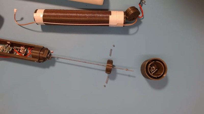
The video below details [Øystein]’s implementation of an ATAS-compatible tuning coil, mainly focusing on the mechanical and electrical aspects of the coil itself, which takes up most of the room inside a 50-mm diameter PVC tube. The bore of the air-core coil has a channel that guides a wiper, which moves along the length of the coil thanks to a motor-driven lead screw. [Øystein] put a lot of work into the wiper, to make it both mechanically and electrically robust. He also provides limit switches to make sure the mechanism isn’t over-driven.
There’s not much detail yet on how the control signals are detected, but a future video on that subject is promised. We’re looking forward to that, but in the meantime, the second video below shows [Øystein] using the tuner in the field, with great results.


What is the loss percentage in transmitting power comparing this to those small autotuners with relay/coil/capacitor -combos?
Hi, thanks for QSO!
Good question. I’m sorry I’m not able to give you an accurate answered to that as of now. Have to measure some more.
Here are my thoughts. The tuner is more flexible in that you can add capacitance but has a downside if you place it on the transmitter side of the coax. You will then have the «wrong» impedance in the coax which give some additional loss. The tuner may also be unable to give you enough impedance for this application.
The coil in the bottom/ as part of the antenna is electrically lengthening the antenna. This is a compromised antenna that is not as effective as a full length would be. Normally you would not use a tuner to match an antenna that is far off the correct length.
I designed this to be flexible I what you use as element. That would play a huge difference in effectiveness.
So I summary. There are two different applications.
The tuner helps to match when you are a little off.
The coil let you use a radiating element that is far from long enough.
Thanks Øystein for the answer! That was well said. Great thoughts.
Seems Basically like a tunable capacitence hat
Well inductance/capacitor hat
Either make the antenna longer or shorter electrically
But at the cost of swr and erp
It’s an interesting design, motorized variable inductors are usually very expensive to buy. Although personally I think I prefer the ones where a metal ribbon is wound off a form with a spiral groove onto a metal spool, because it illuminates the need for the wipers and lead screw backslash. Although, it wouldn’t be as compact and might have other issues, for example, having a metal cylinder near the coil.
If you don’t need the continuous variability, there’s always the decade box like option, automated by using relays to switch in and out different fixed value coils.
Nice article! Thanks for featuring me!
Is the thread pitch of the threaded rod the same pitch as the coil windings? If they’re different, won’t the wipers slip over the windings at regular intervals rather than rolling along each and every loop?
Amazing
This is an inspiring build! Looking back at past portable multi-band loaded vertical projects, I bet they dreamed of something like this at the time. Love that it can be controlled with ATAS. Never considered implementing it in a homebrew application like this. The ft-891 is a great rig for the price too. Great job. Very much what the spirit of ham radio is all about.
The atas protocol is well documented.
It’s a bilevel voltage. Say 3 to 7 bolts goes one way and 7.5 to 14 goes the other way.
I don’t recall the voltages as it’s been decades since I played with my ft857 and a homebrew tuna.
But you can find the voltages online. From there a level shifter is all you need and you can use it to do all kinds of cool stuff.
–Shane
WP2ASS / ex KD6VXI
Ash the joys of phone typing.
Bolts / volts…. yadda yadda.
Great write up, glad to see people still using these radios and the ham spirit still alive.
–Shane
WP2ASS / ex KD6VXI
Does the slider move linearly along the coil, or does it spin to make use of every part of the coild windings?
Is the thread pitch of the central threaded rod the same as the number of coil windings per inch, or whatever unit of measure you’ve used?
Sorry late reply here. No the slider does not spin and makes contact along two tracks across the coil so its not totaly linear, I belive the atas-100 uses 3 contact points that would make it slitly better. I’m currently working on my next iterration and plan to make that follow around the coil to make it totally linear and hopefully make it available in some form for others to build.