When it comes to amateur radio, one size definitely does not fit all. That’s especially true with antennas, which need to be just the right size for the band you’re working, lest Very Bad Things happen to your expensive radio. That presents a problem for the ham who wants the option to work whichever band is active, and doubly so if portable operation is desired.
Of course, there are commercial solutions to this problem, but they tend to be expensive. Luckily [Øystein (LB8IJ)] seems to have found a way around that with this low-cost homebrew motorized antenna coil, which is compatible with the Yaesu Automatic Tuning Antenna System. ATAS is supported by several Yaesu transceivers, including the FT-891 which [Øystein] favors for field operations. ATAS sends signals up the feedline to a compatible antenna, which then moves a wiper along a coil to change the electrical length of the antenna, allowing it to resonate on the radio’s current frequency.
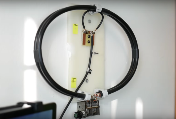
The video below details [Øystein]’s implementation of an ATAS-compatible tuning coil, mainly focusing on the mechanical and electrical aspects of the coil itself, which takes up most of the room inside a 50-mm diameter PVC tube. The bore of the air-core coil has a channel that guides a wiper, which moves along the length of the coil thanks to a motor-driven lead screw. [Øystein] put a lot of work into the wiper, to make it both mechanically and electrically robust. He also provides limit switches to make sure the mechanism isn’t over-driven.
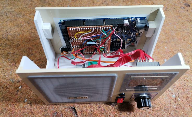
There’s not much detail yet on how the control signals are detected, but a future video on that subject is promised. We’re looking forward to that, but in the meantime, the second video below shows [Øystein] using the tuner in the field, with great results.
Continue reading “Motorized Coil Tunes Your Ham Antenna On A Budget”