The 12VHPWR connector is a hot topic once again – Nvidia has really let us down on this one. New 5080 and 500 GPUs come with this connector, and they’re once again fire-prone. Well, what if you’re stuck with a newly-built 5080, unwilling to give it up, still hoping to play the newest games or run LLMs locally? [Timo Birnschein] has a simple watchdog solution for you, and it’s super easy to build.
All it takes is an Arduino, three resistors, and three thermistors. Place the thermistors onto the connector’s problematic spots, download the companion software from GitHub, and plug the Arduino into your PC. If a temperature anomaly is detected, like one of the thermistors approaching 100C, the Arduino will simply shut down your PC. The software also includes a tray icon, temperature graphing, and stability features. All is open-source — breadboard it, flash it. You can even add more thermistors to the mix if you’d like!
This hack certainly doesn’t just help protect you from Nvidia’s latest creation – it can help you watch over any sort of potentially hot mod, and it’s very easy to build. Want to watch over connectors on your 3D printer? Build one of these! We’ve seen 12VHPWR have plenty of problems in the past on Nvidia’s cards – it looks like there are quite a few lessons Nvidia is yet to learn.


Even wilder option would be soldering a DS18S20 directly to memory module flash if they’re still there..
Perhaps the limit should be < 100C. What is the rating for the connector body?
ABS is fine at 100c, not ideal but far from melting temp of ~200+ and burning temp. The wire insulation might be depending on what the manufacturer used.
But yes Nvidia should have designed in a bigger safety factor in the first place, the connections shouldn’t need to be that hot
Iirc wire insulation is only rated up to 90 C.
THHN/THWN-2 (PVC and Nylon, IIRC) is rated to 90 C in controlled conditions, but only 75 C in humid conditions (hopefully your graphics card isn’t humid)
I don’t know at what point ABS starts to face dielectric breakdown and if that point is
before or after its melting point, almost certainly before. 105 C is the melting point of ABS and that’s WAAAY past what you could use in application, be it electrical or mechanical.
Silicone insulation is rated for 200 C and it’s very flexible at a wide range of temperatures. It’s expensive because it’s not applied as a thermoplastic like the above. The cost per ampere goes down when you use fewer wires of a larger diameter as you simply need proportionally less material. But fat wires are most expensive to put connectors onto.
Combining 2x 6-pin and 1x 8-pin auxiliary power connectors 20 pins total gets you to 300W. And it’s well supported by the current power supply market.
16-pin 12VHPWR gets you to 600W. This is relatively straight forward to add to an existing power supply design, and in some cases only very minor changes were required for a PSU. I kind of wish the safety modifications in the article were just baked into the standard. The more recent update to adjusting the length of the sense pins was a good step, but does not go far e nough.
6-pin 48VHPWR can push 700W (I believe). Requires some significantly different PSU designs and makes for a more complicated set of cables for the end user. This is a very compact way to run your liquid cooled headless GPUs in a tight rack.
At some point one has to hold PCI-SIG accountable for offering options that fail to meet the needs of the industry. And PCI-SIG needs to decide if it serves industrial users or end-users that are plugging/unplugging connectors several times, and are not calculating the strain force when they route and tie cable in their cool gamer case.
The keyword is “glass transition temperature”. 105 C is not the melting point of ABS, but the point where it loses mechanical rigidity and the connectors start to twist out of alignment by any forces on the wire. For wire insulation, the glass transition point is where it starts to turn gummy and the wire can peel itself out of the insulation in certain conditions.
That said, I would not want to be anywhere near the glass transition temperature because plastic creep is accelerated by temperature, and its tensile strength goes down, which means the onset of creep happens at lower stresses. Going beyond 50-60 C has a similar effect where the connector starts to lose shape and the pins begin to twist out of place – it just happens slower over hours and days.
|But fat wires are most expensive to put connectors onto.
Not just expensive, some won’t fit. The connector NVidia uses can only handle up to 18 AWG. Any thicker and you won’t be able to get the pins inside the hosuing.
I don’t know why you all talk about normal ABS here. These connectors are rated for thru hole reflow soldering, so they are not your standard ABS or Nylon plastics you may know from the 3D printer or other applications. Most THR parts these days are made from liquid crystal polymers that have a melting point about 100°K higher than ABS or Nylon.
In fairness if they had just done 12 or 14 (or 16pins) of 4mm Molex (AKA 2x ATX 12v ‘CPU’ 8pins), it would have been totally fine, the problem this time around (50×0) seems to be lack of per wire (or wire pair) sensing and balancing.
I think 48v is a little much. Current (pun intended) VRM designs in 20v for EG laptops are a good compromise, and they may be able to be hotrodded to 22 or 24v pretty easily.
Part of the reason being past 30v is a tingly area that isn’t exactly ‘low-voltage’ anymore.
If your wiring is >90C you already have a problem.
I appreciate that people are stepping up to solve problems with what is obviously a stupid electrical engineering mistake that has a lot of corporate backing. 12VHPWR needs a replacement
this is why i bought a 7900xt. i will never use 12vhpwr on one of my builds.
Yeah if I had to spend that much on a GPU from one of the largest companies on Earth I would expect it to come with some basic features such as “not catching on fire” and “having a power plug that works.” This is obviously recall territory
On the contrary if you can afford $2000+ GPU, you’ll probably can afford it at least twice also when there are no other options on the road towards monopoly. And manufacturer not using that option would be like leaving money on the table.
12VHPWR has 16 pins, and can apply up to 600W.
600W/12V=50A
50A/8=6.25A per pin
The Molex Micro-Fit connectors are specified for up to 10.5A, but that probably assumes the pin, with a contact resistance of 10 milliohms.
Each pin would produce 0.01 * 6.25A^2 ~= 0.4W of heat, which would probably be fine, if there weren’t 12 pins all producing this heat in close proximity. That’s almost 5W in total.
You just made the same mistake as the designers in assuming all the pins are mated perfectly @~10mOhm each. The connector clearly works just fine when mated properly. Note that the connector is rated for just 30 cycles.
See https://www.molex.com/content/dam/molex/molex-dot-com/products/automated/en-us/testsummarypdf/219/219116/2191160001-TS-000.pdf
And
https://www.molex.com/content/dam/molex/molex-dot-com/products/automated/en-us/productspecificationpdf/219/219116/2191160001-PS-000.pdf
im not sure i like the sense pin configuration either. for one its a composite connector that combines molex and dupont style pins in the same connector, this leads to more complicated strain relief requirements and more pins leads to poor seating and requires more insertion force (i hate 24 pin mobo cables for this reason).
secondly the power good and cable present signals together would provide a better information about the connection state if they occupied kitty corner positions at either end of the connector. if one or both signals are bad, then the connection is not secure so dont boot the gpu, throw an error, whatever. however if the corner pins are firm then any pins between them should also be firm (unless your connector is seriously deformed).
the other two signals just indicate the power capabilities of the psu and can be committed or implied in other ways. one interesting thing of note its a 2-bit code and specifies capabilities in 150w increments and it tops out at 600w, so you will need to use multiple 12hpwrs if you ever get an 800w gpu. instead just do multiple cables. i think id replace the old 8-pin with a mini 10-pin, with kitty corner sense pins. and then just use one per 300 watts. power supplies would be required to turn off the power good signal on one or both of the connectors to tell the gpu its pulling too much power. if the cable present pin was also a pwm strobe or voltage divider it could still indicate the power capabilities of the connector while also having a minimum duty cycle/voltage range.
By far the best part is that Nvidia ships a 12WHPWR adapter cables with each card they want you to use. Adapter? I hear you say? Yes! An adapter that a) converts the 12 pins-in-one to four eight-pin connectors that each need to go to a dedicated receptacle on the PSU. And b) (and this is where it gets insane) removes the sense pin functionality by internally wiring them up to power good and 600W on the four eight pin connectors.
Since I have trouble with the card waking up in the wrong power modes likely due to the sense pins this starts to look like a post production quick fix to hide the actual problem.
the fact that they are not respecting their own sense pins says all you need to know. the connector is a boondoggle and even they know it. i feel like the engineers are fighting the execs/marketing on this one.
Not 16 pins. 4 are “sense” pins, 6 are +12V, 6 are GND. There is no load balancing by the card across the six +12V pins.
does a house have load balancing between load bearing walls?
Load-bearing walls do not experience catastrophic thermal run-away when the load is uneven. Parallel wires with uneven loads do not behave like load-bearing walls with uneven loads.
no, they just collapse if one of them gets too much load so they are designed with the expected unevenness in mind
You mean like does structural engineer need to take wind in account when designing a skyscraper or can those calculations just be skipped?
other way around, there is no load balancing so the calculations have to take into account the strength needed to handle the expected worst case uneven load
So it’s even worse, 50A over 6 pins is 8.3A per pin, almost 0.7W each, and 8.3W in total.
How exactly did they expect this to end well?
The problem is if some pins develop 1 or 2 ohms of resistance (not unheard of), this will send up to 20+ amps (measured on camera by Roman ‘DerBauer’ Hartung) down a single wire and contact set.
Hmmm, the #3 largest company on the planet has produced two generations of a product that is demonstrably not fit-for-purpose and are failing in fire.
Why are we not demanding a recall and refund of every single product produced with this abomination of a connector?
How have they avoided the wrath of the United States Consumer Product Safety Commission and it’s international equivalents so far?
Bc we are not their core customer base. For their customers they care about they have cards set aside to overnight, if not same day ship to them, and those customers are probably okay with that arrangement
The enterprise cards don’t use 12vhpwr do they?
They all seem to use EPS power (same as the CPU power connectors) in my experience.
if the cost of a recall is more than the sum of all the law suits and settlements they have to pay out to stay legit, they dont do one.
*that probably assumes the pin can dissipate the heat to the PCB copper plane
Why aren’t we delivering power through card edge connectors yet? All these stupid wires and connectors are nonsense.
It would very likely damage the PCI-E port in the long run and make power delivery very unreliable. Plus, personally, I like to reduce the possible damage to my components and wearing out that port and pumping 600W all the way through the motherboard does not get my positively exited :D
I mean it wouldn’t technically need to be the same card edge connector as the PCI-E… but that is probably what he meant. I agree that I don’t want my motherboard to be passing that many watts to peripherals directly (especially because each new GPU seems to guzzle two hundred more watts than the last one)
I am reminded of that one connector for syncing multiple GPUs with a little ribbon that ran along the stack on the opposide side as the motherboard… Used a card edge connector. I forget what that thing was called
Which one? The SLI connector? Which one of those? 3DFX? At any rate, there are plenty of high quality interface alternatives to what they are doing and they simply decided not to use them.
that would be convenient, i think apple does that. one finger cant push much current but they use a fat finger to spread the load out to multiple pins on the card edge connector. not sure if that makes sense for 600w.
of course you are asking for the power to be routed through the mobo, so mobo gets more expensive and might get toasted when the gpu pulls too much power. another solution would be to add this power rail to the case, outside of the atx footprint, and serve as a forward mounting bracket for stupidly large gpus (two birds with one stone). then the case gets more expensive.
no matter what you do you buck the problem to someone else, and the only people who should suffer for it are nvidia for pushing such a bad standard and anyone dumb enough to go along with it.
It would be possible to add another card edge connector for supplying power, but that just moves the cables from the GPU to the motherboard. It will also make the motherboard more expensive since it will need extra PCB layers to carry an additional 600W per GPU.
A direct connection makes the most sense.
(pcb trace width calculator picked at random, using default (thin) traces) 600W = 50 amps @ 12V wants external/surface traces to be 33.1mm wide. Two because you DO NOT want to share ground with other parts. 66.2mm is over 2.6″ wide. per slot. That’s bad / I don’t see any mobo with enough open space for that.
Plus, now you need TWO connectors which will generate even more heat and more failure points: one from the PSU to the mobo, and another from the mobo to the card.
They just need a better connector.
Server motherboards can handle way more than 600W. They use thick copper planes for power in the stackup tho. PCB manufacturers can even do copper strip embedding for busbars in backplane PCBs, but that’s probably more in the high power automotive market or in some other edge cases where you need a lot of current on a PCB. There are technical solutions. The problem boils down to cost tho. The bad solution we have now is driven by convenience and cost to manufacture.
Not necessarily. ATX standard is 9.6″ in length, and most GPU needing this much power are long enough to go past that length. So have the connector on the bottom, past the motherboard. If the card is shorter have it on the end. Could probably do it with a double sided modification to the SATA power standard by making it one wire longer. 6 wires for each side of the board. Could even make the ‘sense’ integrated by removing one of the 3 fingers on various of the ground contacts.
Anderson PowerPole, XT/AS, and the old standard don’t have this problem.
There’s even XT/AS style (2+4) connectors with additional low current pins either in the center, or offset to a side available from china direct.
A GPU can typically see 1-2 insertion cycles a year for cleaning, re-pasting, or replacement.
And again, PowerPole, XT, and the old standard could handle this. I guess 12VHPWR depends entirely on who’s in charge of QC for each batch.
Whatever happened to wide safety margins for consumer facing standards?
This whole thing is insane at every level.
the atx standards are woefully out of touch with the current state of hardware and need a revision. in lieu of proper standards companies like nvidia will just come up with a solution that works for them and push it forward as a defacto standard. best thing other companies can do is not switch over. then psus get more expensive because they have to ship with 2 sets of cables.
This has nothing to do with ATX at all, it’s PCI-SIG trying to use micro-fit connectors everywhere even when they are no longer appropriate because the industry hasn’t complained, and Nvidia not bothering to use daunting better because they no longer care about the consumer market.
Yeah, I agree…. Using a million little pins for such high-power delivery is stupid. I mean half of them are positive, half are negative, and like one leftover is for sensing or something… Why not just use two big chunky cables and connectors since the dang things use as much juice as a microwave oven now apparently
Why use many small connector when two big connector do trick?
It really should be two XT60s, just make them black. That would solve all our issues.
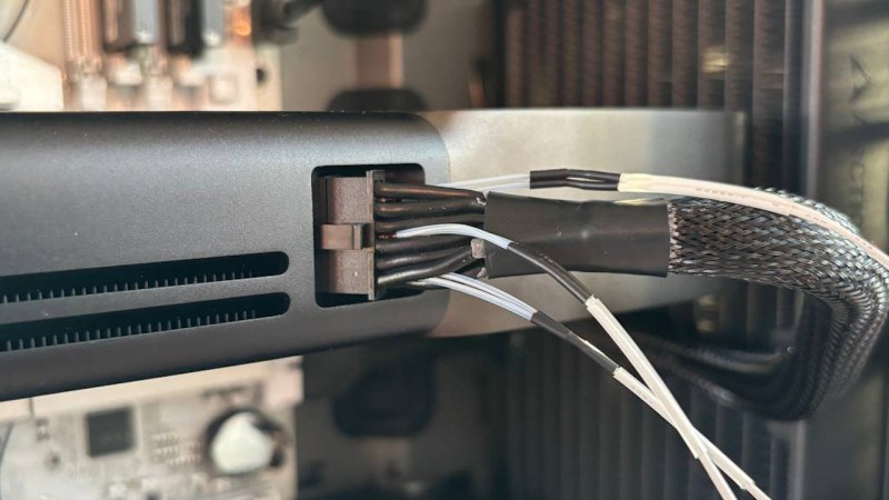
My 5090 I built this watchdog for sometimes wakes up in a lower power state because the four sense pins are now so short in the new spec (inside of the connector on the card’s side) that they seemingly barely make any contact even when the connector is fully seated. So after running FurMark for validation, I sometimes need to reboot to get the full 575Watts the card can pull. The power connector itself is otherwise still fine on my system.
Suffice to say, I don’t think I’ll leave this PC alone, running some massive GPU task without supervision any time soon. This card seems like a bit of a time bomb to me right now… At least mine doesn’t have any ROPs missing…
part of the reason for the poor seating and bent pins is that there are too many pins in the connector, and 2 different connector types. this both increases insertion force and strain relief requirements (and the additional fitment requirements that come with a large inflexible cable when there is a giant gpu in the way). best way is to use one type of connector and put the sense pins in kitty corner positions. shortening the pins is a dirty hack at best.
ive also called into question why we need so many sense wires. 2 of the wires are just a binary code to indicate what power the psu can deliver. one checks to see if the cable is attached and the other is the power good signal from the psu. placing these in kitty corner positions at each end of the housing makes sense. the cable attached signal can multiplex a voltage that indicates the power range. any value above 5v is a good signal. but a voltage divider somewhere between 5 and 12 v would indicate the power capabilities of the psu. this could also be a pwm signal or a one wire serial connection if you ever wanted the psu to have more smarts.
I have literally desoldered a GPU power connector and subbed it with a pigtail and an XT60… just because I couldn’t find the little specialty connector it came with and didn’t feel like ordering a new one. Works great
I love it! Which card was that?
If they could make an XT90 with 16 little pins for soldering into a motherboard . . .
Also this is exactly why EVGA got out. They would have had custom power designs that worked.
I guess the problem with XT60 or 90 is the soldering for the cables is not very friendly to mass production, I’m sure they could figure something out though.
or just go back to multiple 8-pin. or the mini 10-pin (i described in one of my other posts), which is really just an 8 pin with sense wires. one per 300w.
This is still such a silly problem to have walked into…
The commercial cards from all of the vendors use reliable EPS 12v connectors like the rest of the server space for the past decade. An 8-pin EPS connector is rated for ~380w, with an overhead of something like 5A per pin!
This is not a flaw of the connector, but a flaw of expecting a mass-consumer product to operate in a perfect world where pin and wire resistance is not a factor… And then also running it within 1A of the rating… in a system where neither the load or the source device can (a) detect or (b) manage if the power draw is balanced across the pins.
Seriously, for $2000 I would expect that something running the connector within an inch of its rating would have implemented shunts and power phases to make sure that one wire was not able to draw hundreds of percent above its rating. The salt in the wound is that the cards used to have this!
I believe the first-party cards in the 30 series had 3 phases, the 40 series reduced it to two phases, and the 50 series reduced it further to one phase.
And for these new GPUs it’s 12amp per pin or more. While connector design isn’t permitting it (it’s still same molex), there is no enough guarantee on contact surface.
They should not use molex. Instead something similar to XT used in drones, which allow up to 90 amp per pin.
most of these $2k GPUs lack fuses in the 12V rails…they literally cost a few cents and yet most manufacturers can’t be bothered, just let that failed MLCC cap burn a hole through the PCB…
It is really wild to me that they are using multiple conducting wires but only monitoring amperage on them in total versus per conducting pair. That is bush league level engineering and design for high draw power lines. More over, for over 2k a pop, why are we using crappy plastic molex style connectors instead of a plug with positive mechanical latching that must be physically opened and closed and maybe something with some metal parts on the latch instead of plastic? I have no idea how 12vchpwr was designed and adopted but its some how worse than the old PCIe 8 pin molex ones. If this was bargain basement stuff I would understand more, but this is suppose to be the best GPU on the planet.
Please, could anybody explain me, what’s the problem to just desolder that Molex and replace it with something apropriate like a pair of XT60 or single SB50 for 12V power and something small for sense wires?
It could be done in a dozen minutes and will solve the problem completely.
As long as you satisfy the the sense pins is totally fine. Still, make sure you do it properly so you aren’t the problem after voiding the warranty.
Since when hackers should care about voiding warranty? I don’t understand that.
Hackers are not buying these GPU, hackers are putting data center boards on custom carriers with EDP.
Nvidia charging $2,000 and not allowing manufacturers to put 3x 8-pin connectors on the board are the problem. (Some of these GPU are larger than my whole SFF system that has power supply and 4060 inside it!).
In the US they’d still have to prove that you are the reason it broke. They can’t void your warranty because you modify a device unless the modification was the reason for the failure.
So if you swapped the connector and an unrelated component failed then they’d legally still have to honor it.
That may be true but they will still make it hard as hell for you to claim the warranty and likely even wait for a lawyer to send them a letter. $2k is just too high of a risk to do this type of swap unless the connector is already damaged. In that case I’d probably do this myself, too.
With how Nvidia is going, the 60 series cards will have an external 240v plug so you can feed them 2500W.
For real though, I’m surprised no one has hacked together a 12v high power cable using Romex…
In total your PC will consume 3,6 kW (16A @ 230V) but you’ll be able to play the latest $250 AAAA slop, all looking the same, all made in Urinal Engine 6.
Not much of a gamer myself, but I do enjoy training AI models at home.
As for how this warning system should behave, it seems like going straight to shutdown would be undesirable. You might first want it to light up some warning LEDs, then after a while maybe beep a beeper, then request a soft shutdown, then finally do a hard shutdown if the temperature doesn’t go down.
And if that doesn’t bring the temp down, perhaps activate the fire suppression system.
I agree! Good suggestion and a very easy addition! I’ll keep improving it.
Can’t they sense the per-pin power draw even if they are unable to balance the load? Could just have the card refuse to start if some pins indicate too high resistance. I have seen lots of discussion about “load-balancing” but that seems like a backwards solution since the 12V cable are all ganged at the power supply end and at the card anyways.
They cannot because they literally removed the hardware for it. The 3090 could sense three pairs, the 4090 could sense two pairs, and the 5090 bundles them all up into one big pair. So they only get total power.
The load balancing is still needed even if the PSU has the wires all in parallel. Because the card should know if it’s pulling 575Watts through one 16AWG wires or through all six of them. But they can’t, so it overheats, melts, and ultimately bursts into flames
Ammeters with display are $3 each from AliExpress. You only need 3 for safety. Connect them to the reset switch on the motherboard and/or an alarm.
Although a non-contact version could easily be made with some tiny ferrite toroids and either discrete logic or a microcontroller to read the draw, implementing an out of balance measurement to provide a go/no go light. Could even go to a USB header on the motherboard. Could be built by hand with a Rpi2040 dev kit and protoype board for less than $10 no doubt.
In theory a plugged non-moving connector will not be changing in resistance if it has good contact to start with, so this would most likely help on first assembly or maintenance situations. Re-plugging until good contact is made.
I’d rather see non-contact ammeter than a thermal probe personally. Amp measurement will catch the problem sooner than temperature.
This project is good btw, simple, cheap. But why needed on 2,000 product (which is most certainly more than 50% profit, probably closer to 75)
Cool project (there’s a pun in there somewhere) that helps address the issue.
The premise, however, boggles the mind. Would you use a live bunny as a battery warmer in an EV, then layer on solutions to keep the bunny alive and comfortable so the battery stays warm and the vehicle driveable in cold weather? Of course not; you’d use an appropriate and durable solution for the desired end state.
The power connector itself is wrong, wrong, wrong. Every DIY solution to prevent a known-dangerous implementation from spontaneously catching your PC on fire (that’s on my 2025 bingo card, yay) lets Nvidia know they can sell overpriced and dangerous products with impunity.