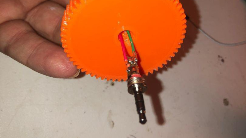
If you’re familiar with electrical slip rings as found in motors and the like you’ll know them as robust assemblies using carefully chosen alloys and sintered brushes, able to take the load at high RPM for a long time. But not all slip ring applications need this performance. For something requiring a lot less rotational ability, [Luke J. Barker] has something from his parts bin, and probably yours too. It’s an audio jack.
On the face of it, a 1/4″ jack might seem unsuitable for this task, being largely a small-signal audio connector. But when you consider its origins in the world of telephones it becomes apparent that perhaps it could do so much more. It works for him, but we’d suggest if you’d like to follow his example, to use decent quality plugs and sockets.
This is an entry in our 2025 Component Abuse Challenge, and we like it for thinking in terms of the physical rather than the electrical. The entry period for this contest will have just closed by the time you read this, so keep an eye out for the official results soon.


Nice idea: never would have thought of it.
It works OK but if you have low signal or something you have to be careful with how fast you spin it. Its a real easy way to add noise to your signal. That said it is the cheapest slip ring I know of.
I’d idly wondered about if for a while, some model makers told me it works ok for “low spec” uses. Apparently common in things like R2D2 models to get power to the rotating head part. Data goes over IR. They do wear out.
So I made a Ferris wheel. Wheel spun on an axle, plugs were inside so there was no load on them. One each side for redundancy. Powered some LEDs on the baskets. Worked fine. Might still be working.
I wouldn’t use that for addressable LEDs, slips rings are pretty noisy and I presume these would be much worse.
To be honest you could bodge up some DIY slip rings that would work just as well or better, but the phono jack is worth keeping in mind.
Now that’s some quality abuse. It’s kinda terrible–I’m sure the plating will wear right off if you spin it for very long–but clever and functional within its limitations.
If you use decent quality connectors, it will probably work fine for something that moves slow and infrequently.
Unless you put a lot of DC current through, because the single point contact will arc and erode quickly. An audio jack doesn’t make a good power connector anyhow.
It does fit with the abusing a common component though!
For me for now clear winner. And for more robust solutions you can use 6.3 mm / guitar jack.
It’s a pretty good idea for low total rotations and speed and, I’d imagine, high noise tolerance.
Somewhere, way back in the dark recesses of what used to be my memory, I recall seeing a 1/4″ phono jack used to implement some sort of rotational contacts. I’m fairly certain that I didn’t hallucinate it…fairly.
there was a magnet in the tip of the plug.
https://hackaday.com/2025/04/28/look-its-a-knob-its-a-jack-its-euroknob/
That’s it!
In my humble opinion there are two major nahs on this:
1. enough rotation and time and the thin metal contacts from the jack receptacle will wear enough to start losing electrical contact;
2. once the thin metal contacts are punctured, the hole will become a one tooth cheese grater/rasp and the jack will be gone, like in the Titanic movie end;
3. electrical contacts are not perfect as they are not designed to work in this situation. Perhaps a redesign of the metal contacts (bent them 45 degrees if rotation is one way – so the jack does not “unscrew” – or 90 degrees for both ways) will make thins a bit better.
For a cheap one off, not high RPM, not to long, it might work.
I suggest this for power only, for data use spdif.
In fact there was a jack with spdif right in its middle. It is called “Mini Plug 3.5mm Male Digital Optical SPDIF”.
Whoa, spoilers!
Everybody knows Titanic went down. Which means also all the equipment on it, including the bells, cranes, sporting equipment, plates, etc, etc, but also all the jacks.
Not spoilers, just logic.
jack/Jack…humor, or attempt thereof
why bother with an spdif, just use an ir transciever in the hub and one on a stator. “black” (to ir, black materials are often transparent to ir) out both to minimize ir reflections. you can move power into it with a matched pair of coils.
also think the death wish remake would have been a better movie reference.
It probably helps if there’s a bearing or some other mechanical bit for retention because twisting an audio plug is a great way to get it to pop out of the socket.
Back In The Day, PL-55 and PL-68 plugs were solid brass. But I haven’t seen any in the surplus sales catalogs for a while.
“Back In The Day” – Thanks pal! Now I feel real old! 😂
I used to work at a company called Astralux Dynamics which made those very brass telecoms jack plugs, amongst other things like sockets and relays and so on.
About twenty years ago, I was playing around with robotics. I built a tracked robot (thanks Tamiya!) based on an RTX2000 (Forth CPU) evaluation board. I placed a collision avoidance sensor (IR LED pair) on a turret. It was rotated with a stepper motor to provide spaced rotation steps. A magnet and Hall effect sensor were used to provide a reference point while rotating. To get power, ground, and two data signal outputs to the turret, I used a telephone cord detangler as a slip ring. It worked quite well for a slow rotation, low current application.
Phone detanglers are great. They are small and have a couple of contacts. In case you need to transmit high power – there’s a slip ring in the cable wind up mechanism of your old vacuum cleaner.
Now that IS useful info. I would definitely read any hacks that make use of this! Thanks for the info.
Beware of the spring when disassembling, this could cause serious cuts!
i think we’ve found a winner.
This summer just gone, I did just that. We had a 120-metre cable on a winding drum, but it needed to be connected to a datalogger. Solution: I used a ¼” jack and socket – the socket was on the drum and the jack plug on the connecting cable between drum and datalogger. Worked a treat 😁
i have done this with quarter inch in a very low rpm and intermittent situation. works very well, but agree that longevity would be an issue if it was really having to spin long term. i was running audio, so low voltage and current, didn’t have as much problem with noise as i was expecting, but there was occasionally something
I used a 1/4 inch plug/socket for this idea for a ’round the pole’ 12v planes in the 90’s. (Think 20cm wingspan balsa plane tethered to a weighted pole with the tethers being the voltage lines, slight up elevator and the motor speed controlled – more rpm = more height (ish).)
Ooh, that’s a neat idea.
as much as folks are sure this can’t take much current, would be noisy for data, and would wear out quickly, I’d love to see some real numbers put to it. Maybe some addressable LEDs being spun with some lithium grease on a decent trs plug at several hundred RPM. If nothing else than to see just how quick it breaks or how poorly it carries data lines.
If you wanted to go full Projecr Farm with it you could try different brands/types of jacks, since I’m sure surface mount ones would be less robust than the stacked riveted bolt-on style ones similar to guitar jacks.
Since this idea was featured a few years ago already (I think I actually saw it on HaD if I’m not mistaking) perhaps we can ask the people that actually used it how it went and how it lasted, instead of everybody here just guessing.
Of course I know it’s more popular to just hallucinate things, but we don’t HAVE to follow the way of the AI :)
Anyone remember the trailer for BigTrack?
That used a jack plug For the mechanical connection, pivot point and power for the tipper.
(Granted it was always snapping off, but….)
This would be useful for scale models and toys. You could have a positionable ladder on a model firetruck with ladder lights.
In Croatia in the 90’s up to middle 2010’s there was a popular autopilot for small boats made by a company which started as an electronics repairmen. The system was designed in the 90’s during the war, and was slightly MacGyvered – the control box controlles a car viper motor which is connected to the steering wheel with a belt and pulleys.
The interesting part for this article is how to set the course – there is a cylindar with degree markings all around the perimeter, which sat in it’s “cradle”. Within a cyclinder is the magnetometer (I don’t know which type and how it works exactly but I know that it was important to set the cradle and cylender as far from metal as possible) and you would spin the cylinder to the wanted course (there is a mark on the “cradle”). The “cradle” had a 3.5mm 3-ring plug pointed up, and the cylinder had a 3.5mm socket on the bottom – setting the cylinder in the cradle would connect the magnetometer to the control box, thus a 3.5mm jack was used as a slip ring.