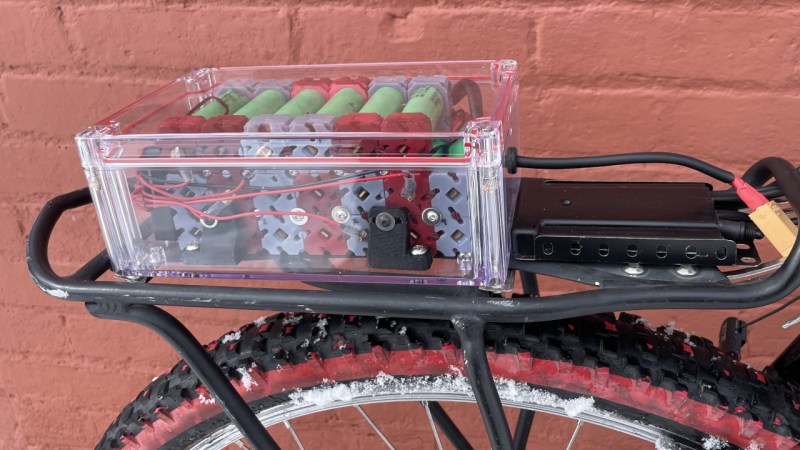
Building a battery pack from 18650 cells traditionally requires patience, a spot welder, and a supply of nickel strip. But what if there was another way? [Ben] is here with Cell-Lock, a modular battery assembly system.
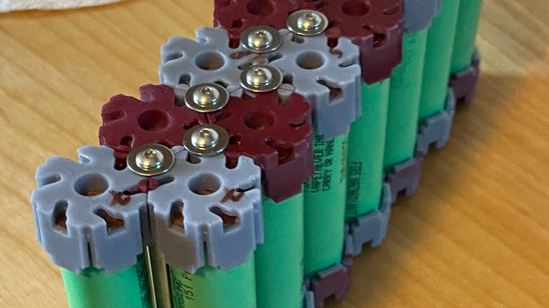
At the system’s heart are a set of interlocking end caps and connection pieces that function as locking cams as well as the electrical connections where needed. They were inspired by the cam systems used for furniture assembly, and are activated by rotation with a screwdriver. The result is a mechanically stable battery system in which different configurations can easily be assembled.
 We like that it doesn’t involve any heat near those cells; in part because we’ve seen our share of dodgy connections overheating. But we do have a few concerns. These include how reliable a connection those cams would make, as well as how much current they could safely take without overheating. If both of those could be addressed, we can see that this is an idea with a future.
You can see plenty of examples on the linked project, including an e-bike pack which seems to return no problems. Meanwhile this is by no means the first modular battery pack system we’ve seen.


Oh, this should be a good topic for comments, after the recent Battle Born experience.
Might even make its own popcorn.
Yeah, looking at screws in plastic and exactly what I was thinking too. Creep is going to kill them.
Realistically? The creep rate is low enough and the compression loading high enough that the creep won’t overcome it and slacken the rods for quite a while. If a battery pack gets maintenance where you tighten the rods every couple of months it’s not going to be an issue. With a modular pack, why not? Clearly you expect to be doing service on it.
Depends on the plastic used, sure PLA isn’t suitable but ABS, ASA or PC doesn’t creep much. Also the construction, plastic in compression rather than tension will mitigate creep problems.
That said… This battery with those large bolts will be significantly heavier than the spot welded strips.
This “solution” is much worse than the problem it tries to solve
Comments section should be interesting very soon.
You pay for that modularity with weight, though.
Do you? 3d printed plastic is usually pretty light.
I haven’t done a good head to head comparison yet, but you definitely loose out a little bit on the overall dimensions, and probably on the weight too.
Aero PLA is extremely light so I very much doubt that; particularly when compared to the weight of batteries.
Not everyone is addicted to the cf filament quackery.
Don’t use PLA. While I’ve been upbraiding people in the other comments for crying “creep! creep!” without even bothering to check what material is being used, PLA is the exception which does creep. Use practically anything else!
I’ve printed out all these versions using “Abs-like” resin. So far so good, but like most of the rest of this project I need to do a lot more testing.
I see the concerns about reliability and current.
He’s using this on a bike and if we can trust him he says it’s been ok so far. That sounds like a good sign for reliability what with bumps and all.
He also talks about temperature and admits to the limitations of what he has tested so far but claims to have plans for further testing by running at a higher current to heat it up.
Obviously peer review is needed but it seems to be off to a good start.
Thanks! You’re (and most of the other commenters) are right that those are the two main issues with the design at present. In their current state the batteries I’m building are good enough (at currents < 20 amps) but just don’t have the reliability that I’m after. I’m currently trying to redesign the copper parts to better handle vibration, but after that I really need to get solid results on how these connectors behave at higher amperages.
Plastic creeps…..
This only works so long as the force on the contact remains. That will be hard to accomplish here.
Not all plastic. And there are countless battery holders out there made with it that aren’t sagging at the lightest touch.
I know what you’re saying but a material called “plastic” not deforming under an applied load is kinda hilarious
“Plastic” in this case is short for “thermoplastic”, meaning the deformation is facilitated by elevated temperatures. Keep it cool, and (ideally) it doesn’t become plastic.
Creep is not a synonym for deform.
All materials deform under applied load. That’s not creep, which is where a material undergoes gradual plastic (i.e. permanent) deformation even when the applied load is well below the limit for immediate plastic deformation.
Not all materials show creep. Not even all plastics.
Most battery holders use metal springs to maintain the pressure.
The springs supply pressure, but what do you think holds the springs in place?
now that you can get battery spot welders for around $30 from lots of online stores, im not sure we need a no weld solution.
Makes swapping in fresh or higher capacity cells so much easier.
Probably should be focusing on high current open source tab design instead then. Make the tabs connect via solder or screw. Spring loaded and high current don’t usually go together, although I am sure it could be done given a ridiculous budget. Using gold or Nickel plated conductors and heavy springs for example.
Do you have a link to the current open source tab design you’re refering to?
No no, high current, open source. Punctuation or lack thereof has confounded you.
We absolutely do. At work we have about 500 15P3S packs. One cell goes bad and the whole pack gets scrapped since it’s all welded together. Creates a lot of waste that’s uneccessary in most applications where 18650s are used.
I have a spot welder that I make packs out of for personal use, but reworking those usually damages the cells, bus bars or both.
You’ve accounted for costs on one side.
Now do the other.
Cost of holder, cells going bad because of loose connections, devices failing from same, extra weight, time spent finding resistance in packs.
Hint don’t try to reuse the bus bars.
its usually a good idea to performance match cells going into parallel packs. series packs need active balancers. if you are doing large pack with a bunch of parallel modules in series, you tend to have to replace the whole module anyway.
if you replace the “bad cell”, the other cells will be worn and will need to be re-rested and re-binned anyway. you can just swap it for a brand new cell, that will lead to a cascade failure of the aged cells. you must replace it with a cell which is similarly worn and has similar characteristics.
im not sure the bus strip removal is as destructive as they say it is. i pull off bus strips with pliers and file down the nuggets flush with the cell. if i need to replace the sheathing i got heat shrink for that. if you re-test after the clean up step, you can validate the used cells for reuse. you can make a new module from used cells so long as the characteristics match.
obviously you need to be doing a lot of refurbishment on a lot of packs before you can start making functional packs out of the salvaged cells. i dont do anything at that scale, i usually just downcycle larger packs into smaller packs for personal use.
ive done spring cups for terminals before, where you have a cup at either end of a 3d printed 18650 socket, inside which you put in a terminal spring with a wire soldered to it. it works, but it adds considerable bulk, if not mass, to the battery pack, and another point of failure. fine for small devices but not every cell of a large pack.
This is a hard problem to solve, but I like people continuing to try to solve it. Every little idea pushes closer to an ideal solution.
Make little battery cases for 18650 batteries that snap together like Lego bricks, make them so you can do series or parallel connections or make sets of series banks into series/parallel banks for higher voltages
No welding required just snap together into any desired configuration
Done, but requires soldering.
The snap together part is just a bad idea.
what about pcb based terminals? you can get pcbs made in any form factor you want (hexagonal or square, series or parallel). surface soldered (or welded) spring terminals to one or both sides. you can use nylon (or electrical, if you need conductance) screws and spacers to clamp batteries between the two boards.
the pcbs can have fat finger edge connectors to connect to eachother or to a backplane (this would be good for parallel modules that slot into a series backplane with the balancer, monitoring, distribution and regulation circuitry all built in.
honestly its not a new idea, i had a power drill battery that i refurbished and they just used cordwood style constriction with cells, a heat sensor and a few bus wires between two pcbs. (though it did use the nickle strips for the battery to battery connections, you can probibly find a spring terminal not much thicker than the foam insulation pads they used).
This: https://www.youtube.com/watch?v=UM3m_qh-Wf8 basically. Although that cheats by having screw fittings on the batteries.
This: https://www.youtube.com/watch?v=_HZJ-R5QzHs is closer to what’s shown. Interlocking plastic frames that add threads to 18650 cells, that you then join with bus bars.
I guess you could get PCBs to work there as well. Add those threaded studs to PCBs and skip the caps.
Bob – I took pretty direct inspiration from the Vruzend sets, I’m really trying to see how simple I can make the full assembly process. I’ve gone back and forth on whether or not to use PCBs on the end caps, and I still am not totally sure. I’m using copper parts mostly because they’re the easiest for me to get manufactured, and I think they’ll withstand slightly more current than most PCBs could. My eventual goal is to get much closer to LEGO levels of assembly, but to do so I think I’ll have to switch to a more suitable material (likely nickel), or go the PCB route.
This should sound obvious in retrospect, but the vast majority of battery systems don’t use spot welded tabs. Usually they use some kind of spring mechanism (think of the average AA bay). Li-ion battery packs are welded because they’re mass-produced assemblies that are designed to be a non-serviceable, permanent pack. They weld it because it’s cheaper and makes a better connection, and so they don’t have to make spring compression part of the design constraints.
The idea that packs produced by individuals would be spot welded is a little silly. The fact that many people do it ANYWAY is even more silly, as though we just assume it has to be that way. We’re not operating a factory, and we prefer our packs to be serviceable.
Nickel-plated springs for battery packs are crazy cheap. Just work it into the design, size your brackets correctly, and slot your batteries in as though they’re AAs.
yeah i think this is the right frame for this project and really brings into focus the fact that the spring tension is being provided by creepy plastic instead of by the traditional coiled (or dimpled?) metal. the core fact to not let go of is that there has to be spring tension, and if it isn’t being provided by metal then it must be provided by something else. There’s no like static position “just touching”, it needs tension, something needs to be deformed.
Not all plastics exhibit creep. And lots of non-plastics do. Pick a material that doesn’t creep, stay below the plastic deformation limit, and it won’t fail.
right but this isn’t a baeklite or polycarbonate battery holder
Currently learning this the hard way: none of the copper designs I’m trying really have enough spring in them. The current copper parts do have a dimple in them for this reason, which works ok for now, but I’m after a more robust solution. Tyler’s point about nickel plated springs is a good one I think, I’ll have to pick some up and give it a go.
Yeah sorry about the lack of photos Miles, I need to clear off the bench and take some better ones. I’m interested in the plate/spring idea, but can’t quite envision what It would look like? Would you print each side of the battery as one single piece and then bolt them together?
While this solution may work for others, it won’t work for me. We are using 120VDC into a 3ph controller to run an aux motor in a sailplane. We can pull a couple hundred amps.
Also, space is very tight, we won’t give up cells to make this fit.
Yes, we spot-weld strips to the cells.
Decades ago we soldered direct to sub-C nicads for RC cars.
Not really there are lots of good reasons to spot weld, even as an individual buying a tool for one project it is pretty cheap – likely cheaper to buy the tool and nickel strips than enough mechanical fixings and springs for almost any battery capacity bigger than portable power brick meant to top up your phone…
You can buy battery springs fairly cheaply, but that still needs the structure to hold them – that is going to be lots of CNC time, even if its a cheap 3d printer’s time. And as that structure has to be able to take the heat build up in the pack and force of those springs and battery shaking around as it does so… For an example where it wasn’t done well enough it seems look at the MNT:Reform laptop – no personal experience but I understand those batteries even in a rather decent looking off the shelf holder just will not stay put in the real world moving about conditions.
You don’t have to spot weld, but in many cases it does make sense.
Or skip welds and springs, and get batteries with threads that you just screw together like high dangerous Meccano. Similar to those big capacitors you see occasionally.
Battery packs with lead acid batteries essentially do the same thing.
Absolutely not you’re talking about drastic variances and increases in the overall batteries internal resistance when you’re adding things like double a slot holders it unfortunately does not work when you start to scale up current. a double A does not produce anywhere near what an18650 does
AA NiCads can put out a decent amount current. Don’t put them in your pocket with your keys.
Your point still stands though.
HaD.io is upside down for people hitting a project for the first time. The project goals/’read first’ is at the bottom. After a read through (sadly there are few/no pictures of the constituent parts; which could/should have made the HaD blog post) I see kind of what he is getting at. If molded from ABS this could be a neat and usable idea. He tests at 10A/40v continuous, which should be good enough considering Tesla uses 15A per cell fusible links in their packs.
It is an interesting idea and he is using custom cut and (self) stamped copper bits for the connections.
Being a very mechanical individual I would like to see the endcaps as a single piece and clamped by a plate of some kind with a steel spring somewhere, even a wave plate style spring could work 🤷🏼♂️. He moved away from the through bolts, but I’d bring those back.
Even if this makes it more of a “custom per pack” deal you can still do the prototypes with his current methods. Also there aren’t that many permutations of cells, square grid or hex/triangle is pretty much it. Yes that makes the whole pack or a chunk of it to disassemble, but at least there is the option.
I suppose you might have a corrosion problem long-term, though iir bigclive’s solution for that with smaller rechargables is to put a dab of vaseline on the battery contacts to keep the oxygen out.
Battery spot welders are amazingly cheap now.