If you want to work with robots you can do all sorts of learning with software and simulation, but nothing quite beats getting to grips with real machinery. That was the motivation for [James Gullberg] to build this impressive robot arm.
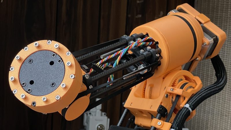
Featuring six degrees of freedom, the robot arm is mostly constructed of 3D printed components. This let [James] experiment with a wide variety of joint and reducer designs for the sake of learning and investigation. The base of the robot uses a fairly conventional planetary gear drive, while shoulder and elbow joints rely on split-ring planetary gearboxes to allow for high torque density with regards to size. [James] implemented a neat sensing technique here, integrating alternating magnets into the output ring gear which are monitored via a magnetic encoder. The wrist joint switches things up again, running via an inverted belt differential.
Running the show is an STM32 microcontroller, which talks to all the encoders, communicates with a Raspberry Pi over CAN bus, and handles all the necessary PID control loops and step generation for the drive motors. The plan is to run higher-level control on the Raspberry Pi which will run a ROS 2-based software stack. Already, the various joints look smooth and impressive in motion.
If you’re looking to learn about robot arms, you really can’t beat building one. We’ve featured a few projects along these lines before. Most of them aren’t exactly production-line ready, but they will teach you a ton about control, motion planning, and all sorts of associated skills. That experience can be invaluable if you intend to work with robots in industry.
My (mostly) 3D printed Robot Arm
byu/SPACE-DRAGON772 inEngineeringPorn
Thanks to [JohnU] for the tip!


Wow!
Looks great! I wonder what kind of load those gears can handle. Either way I want one. Maybe I could finally get a robot to do the dishes for me.
I am quite curious about how this thing really moves. From the 3D printed gears, my first guess is that there will be quite a lot of backlash, and this seems to be “cleverly” hidden in the video by only showing short clips of moves at constant speed. And even then you can see a bit of jerkiness.
I am also having some doubts about the carbon fiber tubes. On themselves such tubes are extremely stiff, but with such long and thing tubes, any movement or flex in the plastic part where they are mounted will be amplified greatly.
One of the better tests for mechanical stability is to just take the end effector by the hand and see how much it moves when you pull and push it a bit. Or with quick start and stop motions. Backlash and flex are very common causes that reduces good looking robot arms to not much more then “demo’s”.
Look like there is a timing belt, and a two stage planetary gear in the shoulder joint and a total gear ratio of around 1:30 and that is a good compromise between force, speed and resolution. Another aspect I like are the arc of magnets. These are almost certainly part of an angle measurement system, and when done properly this can have a quite decent resolution. Use of ball bearings is also nice.
I also like the use of standard nuts in a lot of parts. This is probably stronger then threaded inserts. In some places this could maybe still be improved upon a bit by using longer bolts and putting the nuts “on the other side” so the plastic is only used in compression.
But overall, this design has quite a lot going for it. On his website he mentions that more info will follow soon. So I’ll save a link and come back later.
Wondering how this compares to the Anin AR4 ?
Was thinking of getting one.
How can I get stl files