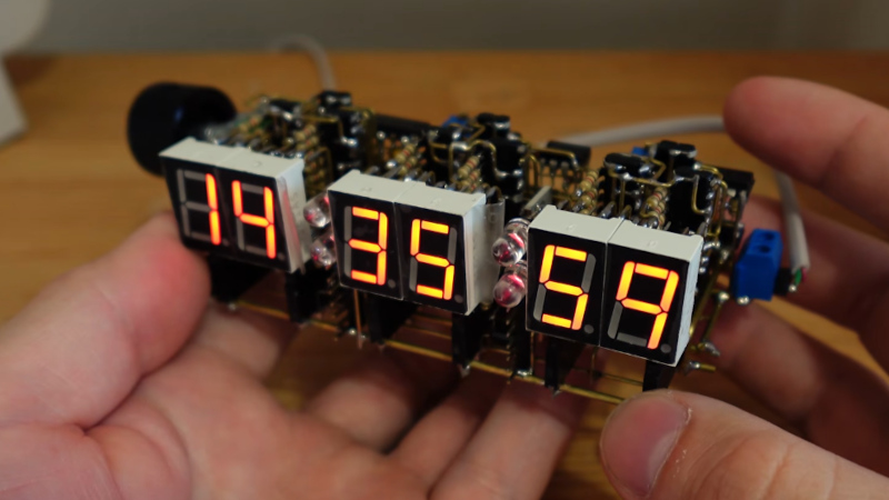
Digital clock projects have been with us since the 1970s, when affordable LEDs and integrated circuits became available. In 2026 most of them use a microcontroller, but for the AliExpress fans there’s one that goes straight back to the ’70s with a pile of logic chips. You can make it on the supplied PCBs, but that wasn’t for [ALTco]. Instead, he made the circuit in free form, using six metres of brass wire.
The construction is anchored together by a set of busbars that carry sockets for a set of seven-segment and driver modules. The circuit is typical for the day, with a crystal oscillator and divider chain feeding the counters for the displays. There are a few clever tricks that older engineers might recognize in order to reduce the chip count. In this case that’s negated by an extra set of circuitry allowing the time to be set from a rotary encoder.
We’re impressed by the intricacy of the device, made bit by bit without a plan, it as some wires what thread their way between others. It’s a truly beautiful piece, and it reminds us of our circuit sculpture contest back in 2020.


Impressive detail in that build!
So going to make one of these now. It looks just awesome
Can I have clock circuits diagram please.
I hacked this clock from 24h to 12h, schematic here
https://hackaday.io/page/399590-24h-to-12h-clock-hack
“it as some wires what thread their way between others”
I stumbled over that part of the sentence.
“It has some wires that” perhaps?
” Man, just another boring bdc cloHOLYCRAP THIS IS AWSOME “
Such care for detail, except for the LEDs: 3mm amber LEDs would have been a better fit !
“it has some wires which thread their way… At least it’s not AI
I make posts with negative sentiment. It happens. This is exactly what I want to see.
I call this “when masters play”. I don’t mean to say the person here is the world best EET or digital clock maker or whatever. What I mean is, this is a person with mastery in the core skills used for this project and they did this just to play with constrained ideas.
Fantastic stuff. We need more of this kind of inspiration.
Having bought one in November. It was stuck on a count*. So I reverse the board using the chip pinouts and a voltmeter for the buzzing out of the chips. Long story longer I asked the vendor for a schematic got the parts list. So since Nov on and off to March 15th, I hand wrote out the schematic. Just this week I asked chatgbt if it could make a nicer schematic from my hand drawn papers. I just finished making a cleaner copy to feed the AI. And boom hackaday has this AWESOME cube of the same thing I just got done with. Between the two of of them I will add both mods.
My kit came with a plexiglass box. I raised the displays by adding a socket. I replaced the s1 and s2 buttons with taller ones that barely popped out the top. I replaced the slide switch with the tallest one I had, but still had to add a socket to get it to be popped out. I also added a USB C port for the power.
* After weeks of smacking it while buzzing it out, dislodging bits of goo from the the solder paste (note to self never again use of SP on thru hole boards) after I had it on paper, I pulled out my portable scope, fired it up and…. It was working just fine! Thanks for the really nice schematic BTW, and I will be adding both of the new features. Karma :)