Interested in taking some wild new 3D printing features for a test drive? preFlight is a free and open source slicer that brings a host of processing improvements as well as fascinating new features and interesting twists on old ones. There are almost too many to list, so here are a few that caught our eye.
Want to mix and match different support types on the same object? No problem. How about use Nip & Tuck seams to better hide where layers start and stop? You can emboss images directly onto print surfaces with a real-time preview and use smart bridging for counter-bored holes. We particularly like the ability to preview a sliced object from the side instead of just by layer. That’s not all, either.
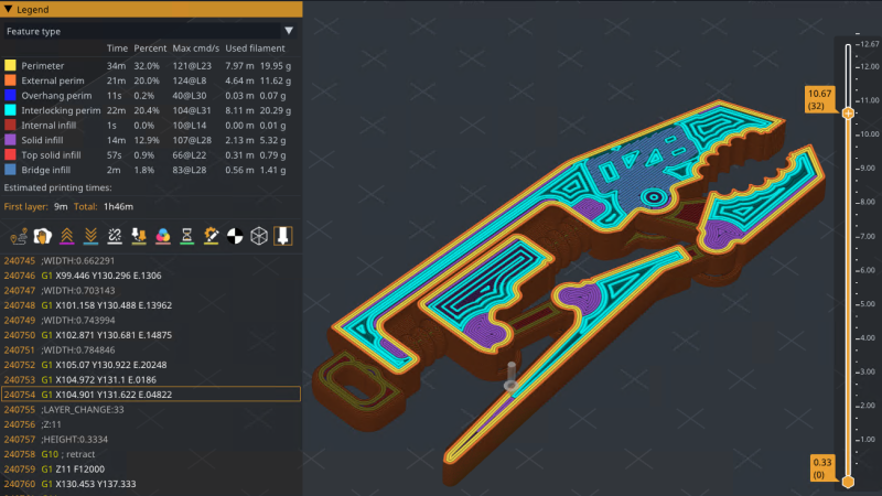
Those features alone are pretty intriguing, but there’s one in particular that is particularly relevant to creating stronger parts. Interlocking Perimeters increases layer bonding to increase object strength. Unlike brick layers, which staggers layers vertically, interlocking perimeters plays with spacing and compression to increase bonding in the Z axis while keeping layer heights constant. This is possible thanks in part to the greater control offered by Athena, the new perimeter generator.
There are plenty more features — like a full Python runtime embedded directly into the slicing pipeline, and a host of export pathways — so check out the GitHub repository for added detail and let us know in the comments if you give it a try.


This is extremely fascinating. Thank you; I had no idea this software existed. I look forward to experimenting with it!
+1 just downloaded…
Hmmmm, the printers I like to use most these days (U1 and Kobra X) are not (yet?!) available in that fork.
But I’ll have a look at those features and hope to see some of them in Mainline Orca one day.
I saw somewhere in my brief poking around today that it supports importing profiles and steps it goes through. It mentioned orca as one source.
I will have to find that detail again so I can try importing the AD5M.
Might I add my desire for importing Cura stuff?
@Jan Prägert: sry, clicked on “Report”. What I really wanted to do is answer :)
I am deep in my Orca bubble, didn’t even know Cura is still actively developed, what keeps you using it?
Jan_w: I use Cura because I started with it and it works for me. STL in, slice, save, print. No fiddling. I print PLA mostly, nothing fancy, so /me is a low profile user.
Other slicers need /me to relearn and find out stuff I really don’t want to know, because, well, the printer is a tool that shall make prints.
Where did you find the download
/me printer not supported. So /me will wait and check back regularly.
What is most interesting to me is that it seems to use bigger lines for infill, I just wonder if adaptative cooling still works well with it. If so I am all in
Man, I really hate when I see an initially promising new project with a big readme and website and have to check whether it’s actually made by humans these days…
Impressive density of inaccuracy here:
“In Greek mythology, Athena defeated Arachne not through greater complexity, but through discipline and precision. We named our perimeter generator after her for the same reason.”
This just feels like a telltale sign of something a human wouldn’t write; plenty of other examples:
“Cap slicing threads on unstable CPUs, restrict to P-cores on Intel hybrid processors, and disable NVIDIA threaded optimization when it causes issues. preFlight adapts to your system, not the other way around.”
Coupled with one contributor which is also replying to issues … I guess I’ll ‘wait and see’.
AI assistance isn’t neccesarily a bad thing, I managed to create an IMU to 8×8 RGB array motion visualiser with GPT4, the extent of my input was pretty much requesting features and configurable parameters, describing when things weren’t to my liking, and replacing pi in the circle calculations with the number 3. Oh and of course copy pasting errors with no understanding of what they meant and providing no context to the AI.
The extent of my programming experience was bodging a handful of example arduino sketches into something slightly personalised.
The slopgenerator figured out the rest, including finding two bugs in the IMU library that would otherwise have stopped the project in it’s tracks, I would have had no clue how to troubleshoot and would have assumed I had made a mistake.
The final result was a live motion reactive smiley face running at over 100FPS, built from three partial circles, some mirroring, with adjustable gravity and fade effects, with of brightness the lit LEDs controlled by jerk and acceleration, also referencing LUTs to calculate the colour scheme.
If it truly is a one person project, I’d rather that person be concentrating on the functionality rather than wasting time on the promo material and github readme. If you hadn’t realised, the amazing bumpmesh.net by teachingtech was AI assisted, and I don’t see anyone complaining about that!
We are, admittedly, a small team – and we won’t hide that the launch of our website was massaged by an agent. We took your comments to heart and just spent our Saturday reworking a lot of it. While preFlight was only publicly launched a few months ago, it has been under development for well over a year. We pushed 16 releases in less than 4 months to finally bring it to a point where we felt confident promoting it to v1.0 just yesterday.
I have long thought about combining topology optimisation and slicing in one go to achieve optimal FDM printed part strength. TO is great for isotropic materials, but with the huge leverage slicing decisions have on local directional strength/anisotropy, I can see potential in unlocking extra performance in designed applications. Two ways I see this being implemented: either as extra decision variables and constraints in the TO (for example each volume element’s directional strength depends on neighboring element’s orientation, mimicking continuous line and layer binding behavior), or by including information on designed loads alongside the .stl file, which the slicer takes into account to best allocate material for performance. Perhaps an add-on which lets the user place design loads in the slicer directly?
Have any of your considered this or worked on a similar problem? Looks to me like the next evolution in FDM printing/slicing.
All of those features, and more, are very common in proprietary slicers which are tightly integrated with and even required to operate many defence/aerospace tier printers.
Unfortunately that means the processes and algorithms are likely under patent, so if implemented in consumer/open source slicers the devs would be served cease and desists and other legal threats by Stratasys and the like. We’ve already seen similar situations happen with brick/Zstagger layer implementations.
Releasing a jacked-up fork of Prusaslicer is definitely one way to get your name out in preparation of unveiling your own “Elevate” 3D-Printer design.
oozeBot is definitely on my radar now.
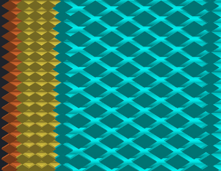
I’m very interested in the interlocking perimeters for some thin wall functional parts I build. But, my brain is not grasping how it works. Spacing and compression: spacing how? Compression where?
Z-height is not manipulated, so horizontal spacing is manipulated to create gaps between lines maybe? Overextrusion on the layer above then pushes (oozes?) plastic into the gap below?
For some reason, I’m not making any sense of the lattice looking picture.
If nothing else, I do like the cross sectional view. It’s kinda cool. You right click the object when viewing it from the angle that you want to see it from. “Clipping Plane” then cuts a plane through the part normal(?) to the viewer’s perspective. Then you can push and pull that plane through the part, while also being able to traverse the slices vertically via the typical slicer slider.
Likewise, I can’t make sense of their written description or images. I’d like to see a simplified graphic rather than the slicer preview screenshot.
I THINK what they are trying to draw our attention to in the cross-section image is the leftmost column of blue lines. It’s an additional inner shell that this feature adds. It alternates thick/thin as you move vertically. This might provide some inter-layer adhesion since the thick lines overlap into the layers above and below?
If I understand correctly its pretty simple. Print a layer and leave half of the perimeter lines unprinted in an alternating pattern. When the next layer prints on top of a missing line it prints with 200% extrusion rate. This fills in the gap and creates a line 2 layers thick. Seems like an excellent idea to me.
We have updated our website to hopefully better explain Interlocking – https://preflight3d.com/features/interlocking-perimeters
From the link: “5-15% estimated Z-strength increase with no time or material penalty.” and further down: “The beads generated over the previous layer’s interlocking beads are printed in an alternating pattern at up to 200% flow”
Good catch – we’ve clarified this on the site: “The interlocking shells occupy the same space that additional perimeters would. Compared to filling the same area with regular walls, there is no time or material penalty.”
From the website: “each layer’s beads fill the previous layer’s gaps”
Thanks! That seemed like the most reasonable approach that I could extract from the previous description. I was finally able to spot what was happening by looking at a sliced object layer by layer with the feature turned on.
I’ll try it out.
I like the look and feel of the app, too.
I tried this out. All I got was “unknown file error” on the prusa MK4S. Doesn’t work out of the box for me, and I’ve no idea where to start debugging. Hard to believe they haven’t tested it on prusa
preflight is compatible with the MK4S. We would appreciate you opening a GitHub issue to better understand this and provide a solution.
What’s the reason you didn’t bother with supplying any profiles for bambu printers?
I know they’re in the doghouse with the open source community cause of the recent behaviour towards the orcaslicer devs, but that doesn’t mean you should punish the owners of their machines. They are probably some of the most common printers in circulation today, especially the A1, P1 and X1 models.
If anything, having another alternate slicer alongside orca would hurt bambulabs rather than help them.
Instead, I’m about to risk breaking my printer by using a slopgenerator created profile/config bundle, and if it goes really wrong I doubt I’d ever consider using your slicer again.
Sure it wouldn’t be directly your fault, but indirectly it kinda is from my perspective, because you didn’t provide a profile for the most popular printers around, yet provide dozens of profiles for brands and printers most people have never even heard of.
Our initial profile set was inherited upstream, which is why you see the brands you do. We are not making any statement about Bambu by not including them.
In the meantime, preFlight supports Orca profile import which should get you most of the way there for any Bambu printer. Profiles are community-driven and we’d welcome contributions from Bambu owners who want to dial them in.
The first thing I did was try to load my exported profile from orca, but got a rather undescriptive error message.
Could you at least provide some example zip packages to use as a reference? It’s all well and good offering a bunch able to be downloaded and unpacked within the program, but they seem to get automatically unpacked so I can’t compare what I got out of orca, to what preflight is expecting.
When I exported printer zip bundle from orca and tried to load it, I got a rather vague error:
“No vendor .ini file found in the ZIP archive.
The ZIP should contain a vendor .ini file at the top level”
I understand I need a vendor .ini file, but there is no context as to what that file should contain, where I might obtain it, or how I would go about creating one from scratch.
Sure there’s probably some precedent to what it should contain, and maybe that’s common knowledge for people who’ve written custom configurations before, but without prior knowledge I don’t even know where to start.
I do appreciate all the work you’ve done on the slicer, I’d just really like to be able to use it too!
That’s a lot of complaining about something that is open source and being made and given away for free.
One minor complaint, the only thing there’s a lot of is justification and explanation why I feel like that, if you look at the rest of the comments I was defending the likely use of AI assistance in development.
Just cause something is free doesn’t mean it should be entirely immune from critique.
We cannot respond to your last message – I guess it is too deeply nested. Please consider opening a GitHub issue and/or emailing us at support@ooze.bot for additional assistance. Thank you
Is that imgui
AGPL licence an backed by an LLC? Stand by for Business Source Licence pricing plan and following rugpull. A lot of startups have come to use the AGPL for it’s legal radioactivity, allowing them to openwash their product without cannibalizing sales of paid licences.
preFlight was originally built solely for our printers – period. But we made the decision to both give back and invest in the community we’ve been part of for well over 10 years. Brand recognition and community trust is how a small company earns the right to sell hardware, and that’s our mission.
As for the license – AGPL is inherited upstream from Prusa, whom we admire and respect. The codebase is a derivative of their work, which we can’t relicense even if we wanted to. We are in business to sell printers, not software licenses.
This thing is unusable under linux. Terrible gui colors. It’s total mess, for instance: I choose 1 or 2 percent infill and it generates 100% infill. And is very very slow. Idk who wants to use this just for the couple of experimental functions.
Thank you for giving preFlight a shot. We are sorry you are not having a good experience. The slowness is likely due to anti-aliasing or other performance tweaks that need to be adjusted for your system – these are found under Configuration > Preferences > Performance. We welcome the communities feedback – both good and bad – as it is the only way we will improve. If you are willing, please consider opening GitHub issues and we’ll be sure to make it right.
@Oozebot – I Tried importing my Orca configurations at the startup but those are NOT compatible as Orca does not have a vendor ini file in any of their export formats. I might try this slicer out at some point, but I will need to find the time to completely manually get my Creality K1C configuration into the software.
What does it take to get Orca configs to actually import without the ini?
If you exported your Orca profiles correctly within the app, it should import. There is a specific “Import OrcaSlicer Bundle” option at the bottom of the File > Import menu that must be used. If you need further help, please open a GitHub discussion and/or email us at support@ooze.bot. Thanks