You could make a clock with three hands spinning about nested central shafts. If you did that, we probably wouldn’t publish it on Hackaday unless you really found a way to make it interesting. Make a clock out of voltmeters, however, and that usually catches our eye. [lcamtuf] has done just that.
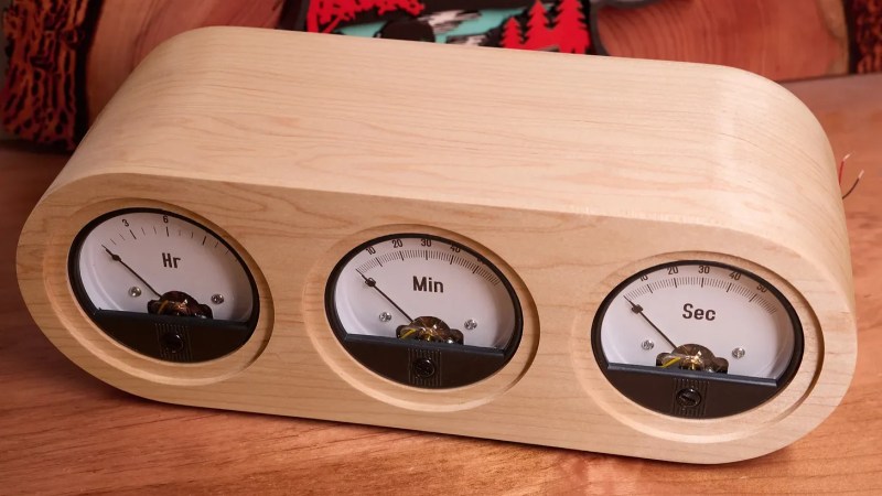
The heart of the build is an AVR128DB28 microcontroller, an 8-bit microcontroller that is still currently in production. It runs at 8MHz, and drives a series of three Baomain 65C5 voltmeters to display hours, minutes, and seconds. Each has a custom printed face with the correct number of 13 or 61 divisions as needed. The voltmeters are driven by a continuous stream of 1-bit pulses with a software-controlled duty cycle determining exactly how far the needle moves. Yes, it’s using simple pulse width modulation, coded by hand by [lcamtuf] to do the job. All the components are wrapped up in a beautiful wooden case, with delicately kerf-bent panels to create the attractive curved lines.
We’ve featured similar builds before, too. As it turns out, hackers just really love clocks and old-school dials. Video after the break, which is worth watching for the rollover behaviour alone.


Very nice, both on the technical and craftmanship. There is just one thing with these clocks, I like a smooth rising and falling so I find the “reset” jarring. What would be really cool is to have the clock faces made with epaper and when the arrow reaches one end the clock face itself changes and then the arrow slowly goes back to the other end, if you understand what I mean. I’m too stupid to build one myself but it would be cool to see.
“… I like a smooth rising and falling so I find the “reset” jarring…”
I think this is a very pretty clock.
I agree with your remarks about reset… I was a rather surprised at the relative violence with which the needles drop.
These are probably inexpensive movements with little damping.
On the plus side I think the issue could be easily mitigated with a small capacitor across the terminals of each meter movement.
It could be fixed in the code too.
Oh yes, very pretty clock.
I quite like the jarring reset. I have a flip clock in my office and when the hour drops it make a rather loud noise. Even the minute flaps make a bit of noise. It’s kind of a metronome of sorts albeit a very slow one. Such a beautiful build.
Respects to trying ePaper. I think the point of voltmeter clocks is the use of “retro” meters to show time though.
re: “the correct number of 13 or 61 divisions”
At first glance this makes sense inasmuch as you need (n+1) lines to delineate (n) spaces, but it also means that this clock counts time from 0:00 to 11:59 (as you can quite clearly see in the video or article).
I mean, it’s still dead simple to interpret and perhaps more logical than the way a traditional clock face works, but surely I’m not the only one that thinks it’s weird for a 12-hour clock would have a zero hour instead of a twelve?
(and yes, admittedly you could “fix” this just by labeling the beginning of the hour scale as “12” instead of “00”, like a traditional clock, if you really want to confuse everyone)
Thanks to the Romans for creating this mess. Clearly we don’t know how to count where we still use a non zero way of counting.
If only the number (is it really a number?) zero had been invented sooner……
Or use metric time.
I have a digital clock that, when set to 12 hr (am-pm mode) displays half past midnight as 0:30 and half past noon as 12:30. I think many clocks do this which is just as illogical.
that has to be the dumbest video showing off something I have seen in my life.
I don’t see what’s wrong with it. i like how it shows the needle reset. makes me wonder why nobody commercialised 360 degree voltmeter dials, would be more suitable for these projects.
A 360 degree voltmeter dial is a neat idea. You could make it like an airplane altimeter, with two or three hands to combine all the dials into one. Each could be different lengths to indicate decivolts, volts, and decavolts.
Then, if you mark the dial in twelve divisions instead of ten, it would make a very fine clock that shouldn’t take much practice for older users to read.
Put a pointer on a step motor.
Because that would require more parts and more complex mechanics. And a 360° “voltmeter” for clocks is called a clock.
It irks me that those meters are not critically damped. Some would consider me unreasonable for that, but they would be heathens.
[Author here] For $9 a piece, I expected the renowned Baomain corporation to do better. But seriously, I think that the dramatic drop makes the clock more fun. When I built the first version back in 2019, I spent a while wondering if I should compensate in software, but decided resoundingly against it.
Assuming those are normal d’Arsonval meter movements, the damping would be up to the driving circuit. If the driver had lower output impedance they wouldn’t bounce so much. And you’re right. Definitely heathens.
They wouldn’t bounce if the code ramped them back to zero at an appropriate speed.
Using the term appropriate speed indicates you don’t really understand damping.
Re: driver impedance: Righto. The PWM driver presents an open circuit when it commands the meter to zero.
Simply placing a single resistor in parallel with the meter coil will damp it. The value of the resistor to achieve critical damping depends entirely on the meter characteristics, and might be lower than the driver can tolerate.
Ach. Sorry: correction. The AVR drives high and low, so not open circuit, doesn’t behave as described here. This meter might not be able to be damped with just a resistor.
i made a clock based on a series of half-adders spelled out with discrete 74xx chips driving blue LEDs (back when blue LEDs were newish), clocked by a 555. Obviously, it couldn’t really tell time because a 555 driving an RC network is the opposite of temperature-compensated. Instead of putting a proper oscillator on it, i just left it in the basement as a night light. It lasted in that role for about 20 years until the power supply burned out. Pretty good night light.
Had one of these for over a decade now… https://www.awkwardengineer.com/
During the initial design it was debated at having 0..12 or 12, 1 .. 12 and the opinion was 0..12 looked better.
[Author here] This idea has been around for much longer than that. This one is timestamped 2007: https://makezine.com/article/maker-news/the-chronulator/
Which is pretty much why I never felt compelled to write about my first build in 2019. And this one is pretty much about the looks, not the electronics inside.
I’ve heard of flyback chronographs on watches, but not the whole clock itself. This is pretty cool, but I would have noodled a little more on those needles flying back. If it’s PWM on the way up, why not reverse it on the way back?
Color me surprised, a not-Youtube video on Hackaday. Though the Vimeo player could do with a “copy video URL” option.
You can get the URL by holding down on the video and copying the inbed code and deleting most of the unnecessary stuff — if you’re on a phone.
https://player.vimeo.com/video/1192897862?h=5c9c9e28be
I was looking through a pile of old bakelite voltmeters and ampmeters in a junk shop quite a few years ago, when the thought of making a clock out of them suddenly occured to me, I’d never seen or heard of such a thing, but the idea gripped me for a bit, but with nothing suitable in that junk shop or on eBay, after a while I forgot about the idea! It gave me great pleasure to watch your, nicely done.