Although the basic principle of radio direction finding is easy to understand (measure the phase difference between different antennas, then calculate the angle of arrival from this difference), the radio hardware to actually implement this has historically been hard for hackers to access. The QuadRF project aims to change this by building a phase-coherent four-channel SDR which makes direction mapping easy (GitHub repository).
The QuadRF uses two boards: one to receive and pre-process radio waves, and a Raspberry Pi 5 for additional processing. The RF board has four patch antennas, each capable of either transmitting or receiving in the 4.9 GHz to 6.0 GHz range, with switchable right- or left-hand polarization. For on-device processing, it uses a Lattice ECP5 FPGA, which uses two MIPI cables to connect to the camera and display interfaces on the Raspberry Pi. These form a very high-speed data exchange, and after further processing, the Pi can pass data on over Ethernet or Wi-Fi. Individual QuadRF boards can connect together in a lattice grid to form larger phased arrays.
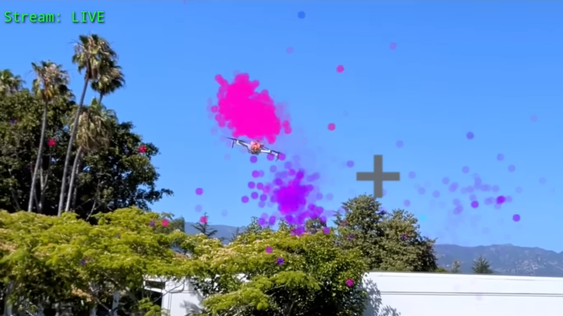
The QuadRF’s software shows off its real strength: it’s compatible with standard programs like GNU Radio, but it also hosts a few of its own programs. The most striking of these is an “RF camera” which scans its entire frequency range at 30 fps, tracking the direction of detected signals and visualizing them on a spatial plot. When overlaid on a camera feed, this plot lets one easily see the radio signals emitted from electronics; as an example, the creators tracked a drone in flight, even distinguishing the two radio transmitters on the drone.
This isn’t the first multi-antenna SDR we’ve seen, though this is the first that could transmit. It’s important to be careful, though: some applications of this kind of hardware run afoul of arms regulations.
Thanks to [Swake] for the tip!


Frequency and phase agile, tracking multiple airborne assets at 30 fps, capable of megawatts of effective radiated power.
I’m gonna bet their target market is not limited earth-moon echo enthusiasts.
KrakenSDR was doing passive radar which is specifically ITAR controlled. QuadRF is normal beamforming which is common in most Wi-Fi routers.
I can already see the arms race between militaries using this to sense the position of autonomous drones from either their C/C signals, or EMF from the drive motors, and drone manufacturers shielding the electronics on their drones to reduce the effective EM signature to those detection techniques.
WW3 is going to suck.
Because WW1 and WW2 definitely didn’t suck.
Where did he write that
Dyson goes to war.
What does he mean that it scans the entire C band? What is outside of that C band? Can information be transmitted through those frequencies too? I have so many questions about this video. I want to get one of these kits and tinker with it. Looks like it could be a lot of fun. Although I am worried about potential misuse. I bet you could set drones up to autonomously fly and identify each other for spatial awareness as well as other say opposing drones. They could be used for all sorts of autonomous surveying or monitoring applications. The legality of a lot of this things capabilities seems be a bit questionable though. I would need to do some more research before I get one of these excuse I could see myself getting into some real trouble lol. Cool video man, Google sent me down this rabbit hole.
C Band is 4 to 8 GHz. This device actually supports only 4.9 to 6 GHz.
What you’ll find there is mainly Wifi. But not the cheap Wifi devices.
For the targeted price I’d buy one if much lower frequencies were supported as well. I want to see all those IoT gadgets. I don’t even care about transmitting.
Civillian FPV trasnmitters for drones use a lot of 2.4 and ghz 5.8ghz – they’re part of the ISM band.
So being able to DF is quite useful in many contexts since it is widely used for wifi “drones” as well as other hacked together tech/IoT.
It would be much more interesting if it could support frequencies below 4Ghz.
It would be practical to support down to about 2Ghz, maybe even 1Ghz; but practicality starts to limit it the lower frequency you go. Higher frequency waves require smaller antennas and small distances between them, so receiving multiple signal received and comparing them is much easier at higher frequencies.
All the processing is done in baseband, so it’s not a big deal to pick whatever band you want — just change the mixer frequency and filters. The biggest change would be the mechanical size of the antenna array.
It’s (mostly) open source: Have at it.
This is exactly my imagination of phase-shift radio waves 2d visualisation. 4 WiFi SDR receivers and vision through walls is reality?
How do I buy this?
Click on the links in the description and navigate to the crowdsupply page…
I’ve always wondered what the world would look like if we could see any portion of the EM spectrum – from shortwave to x-rays (in small sections, of course).
I’ve got some good news for you!
I wonder what kind of eyeballs a biological creature would realistically need to evolve to see x-rays. Would be a fun science fiction story
That environment wouldn’t be any fun.
Not after the first few sieverts anyway.
That’s why aliens have antenna.
A very impressive demonstration & personage:
1. Young American Engineer.
2. Specialist in Rf, microwave, and antenna (pased array) science & application.
3. Speaks a language hitherto thought to be extinct in the aftermath of the expropriation of the industrial process here in the U.S. (yes, we actually did engineer & manufacture radio’s here at on time).
A very impressive young man indeed…..with excellent, well thought out aims & goals…..a real Rf guy!
Well that’s awesome.