
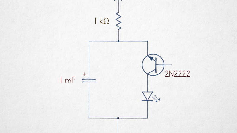
Back in the days when an integrated circuit meant a simple but expensive device such as a 741 or a 555, most electronics enthusiasts made do with discrete transistor circuits. The common emitter amplifier and its variants are the most familiar, but the humble 3-legged device can do so much more. A particularly obtuse circuit is the subject of examination by [lcamtuf], the reverse avalanche oscillator. A 2N2222, a capacitor, an LED, and a resistor, the transistor is the wrong way round, and there’s nothing on its base. Yet the LED flashes, what on earth is up!
The answer lies in avalanche breakdown, the behavior of a reverse biased diode junction as the voltage across it increases. Eventually the electric field reaches the point at which an avalanche of electrons crosses the depletion layer, and the junction conducts. When connected across an RC circuit, the voltage in the capacitor slowly rises to the point at which avalanche breakdown occurs, and the capacitor abruptly discharges. As the voltage falls the avalanche conduction stops, and the cycle repeats itself. It’s a relaxation oscillator.
We’re treated to an explanation of why a transistor behaves this way and why a simple diode doesn’t, due to a “hump” in its I/V curve, and why the emitter-base junction has a lower breakdown voltage than the collector-base. It’s one of those circuits which looks as though it shouldn’t work, but never fails to oscillate.
Want to know more about transistors? Do we have the series for you!












Just wondering if the avalanche breakdown without any series resistor woudn’t turn into permanent breakdown for both BJT and LED. Or is the resistance of this breakdown channel high enough?
Without a series resistor to limit the current, dissipation will be so high that the BJT and LED are turned into an instant smoke generator. And after the magic smoke has escaped it does not work no more at all.
Chinese toys used them for years. They dont always last very long, but we used to put them in dummy cctv boxes. That’s until dedicated led flashes running 1.5v arrived.
lookmumnocomputer built a 1000 oscillator wall with this setup. starving them is quite interesting
The classic “negistor” circuit!
Would probably last a bit longer if there was a current limit resistor on the LED.
There is a 1K resistor in series…
That limits capacitor charging current. When the transistor avalanches, the capacitor discharges to LED with no resistor to limit LED and transistor current.
Eh, it’ll be fine. Not much energy in the capacitor and the voltage drops pretty quickly as well.
It’s a bit like noticing that remote controls can pump an amp thru that IR LED, a tad higher than the usual 20mA. So long as the max power rating isn’t exceeded, it’ll keep working
Thinking about it, the capacitor voltage won’t drop all that much before the transistor “switches off”. Still, LEDs tends to survive short high-power pulses.
There is a low power 12V version of the circuit. 220k- 470k resistor, 1uF capacitor and ELINE 2sc3330 transistor.
For replacements:
ELINE 2sc1740 works with 100k,
early TO92 2sc1740 do not work.
2sc945 or 2sc1815 work with 18k resistor.
Wow, a possible solution for making a solid state version of my father’s nothing box https://www.nixieneon.com/main/fathers-nothing-box/ is that cap in millifarads or microfarads?
Millifarads would give a reasonable flash rate. Having just looked at a schematic for an antique radio, my first thought was microfarads.
Great article :-)
For a simple example (2N3904+1kohm) see https://entertaininghacks.wordpress.com/2024/03/16/practical-traps-with-a-one-transistor-audio-amplifier-solderless-breadboards-and-oscilloscopes/
Can you work out what is happening and why, before reading the explanation?
had to look at the schematic a few times before i could really appreciate the weight of that ‘m’ in 1mF
As an old timer who learned electronics from my Dad and dabbles in antique radios, there are a lot of terms in my head that have long been replaced by international standards.
Microfarads can be MFD or mF, pF can be micromicro Farads (micro mikes). My most recent adjustment is nano farads.
Ms List should know that earth is down. :D It is in the schematic given anyway.
Linked lcamtuf page crash my mobile chrome browser. Knowing who lcamtuf is – that’s very suspicious…
Burkhard Kainka wrote about that in 2010.
https://www.elektronik-labor.de/Notizen/NPNkipp.html
Next logical step, negistor-based joule thief running off discarded AA.
Point being won’t tunneling be better controlled with the base injection from a joule thief coil? I mean, the potential is there, add a coil and make it work even better/faster?
Sorry for opening yet another rabbit hole. Weekend is coming.
Ah, negative resistance circuits! I once wanted to better understand how the Lambda Diode worked (check it out, it’s amazing for RF oscillators!) and found myself immersed in a rabbit hole of circuits like this one, others based on neon bulbs, tunnel diodes, etc. Fun stuff to experiment with.
Dockable electronics
https://www.nanowerk.com/nanotechnology-news3/newsid=69817.php