
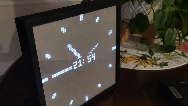
This custom enclosure for a 64×64 RGB LED matrix by [Davisan1001] not only provides a mount point for a Raspberry Pi, but presents a clean and smooth face with square pixels thanks to a 3D-printed grid, some parchment paper, and a sheet of clear plastic.
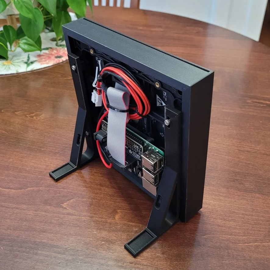 The first clever thing in this design is the way [Davisan1001] created the grid that acts as a light blocker for each LED in the matrix, preventing light from “spilling” over into its neighbors. Instead of designing the grid from scratch, the solution was just to leverage slicer settings. By printing a flat square with a grid pattern infill and zero solid top and bottom layers, the slicer creates the grid all by itself. A little trial and error was required to get the spacing just right, but it seems to have worked out fine. We’re not sure it’s better than designing a grid in CAD, but it was certainly a clever way to avoid having to do so.
[Davisan1001] also struggled to find an effective and economical solution for a diffuser. Certainly, high-quality diffuser films are available for sale, as are specialty acrylic sheets, but surely there was some household DIY option to do the trick. A sheet of plain white paper blocks too much light. Wax paper handles poorly, and off-angle viewing is poor. The sweet spot was parchment paper.
Parchment paper is commonly used in baking and is thin, easy to handle, flat and even in color, and just opaque enough to act as an effective diffuser while still transmitting enough light to not impede clarity. Cover the LED matrix with the 3D-printed grid, lay parchment paper over that, cover with a sheet of clear plastic, and the job is done.
Light diffusion can be tricky to get just right in a DIY project, and what works for one application won’t necessarily work for another. Our community had loads of suggestions on different solutions, so consider this one more idea to try the next time you have a project that calls for it.












There’s no mention of who programmed the clock, it’s not even one of the practice projects on Adafruit, but it appears to be showing 2245, instead of 2154.
The time is correct it’s the hour and minute hands are transposed.
It’s an design originating from clock towers that only had an hour hand in the olden times, because that was all the precision anyone needed. Naturally that hand was as long as possible. When a minute hand was added, it was made shorter.
It still doesn’t look right, though, since the “hour” hand is pointing straight at 9, when it’s about to be 10. It’s not like the hands move discretely, either, since both of the other hands show intermediate positions.
I did this, but I used oak veneer as the front “diffuser” so the lights shine through the wood magically. Looks great.
If the same print that was used to generate the grid had a bottom layer or even two made of white plastic, it would make a perfect diffuser. Especially if printed on a matte build plate. Switch to black at the first grid layer and there you go.
Now for a speaker so it can give you UTC call-outs in Middle English.
No 3D printing, though…it doesn’t hold up to jousting…got PETG shards right through the visor.
The hour hand on an analog clock is the shortest, and it’s sitting just before 2. Next is the mid-sized minute hand at 54, and the longest is the second hand at 45, so in 15 seconds the clock will tick over to 1:55 or (13:55 if it’s afternoon). I’m not sure why it’s showing 21:54 on the digital readout
I find that laminating film works well as a defuser ( the type that is used in larger machines).
If only there were some way to increase contrast and make the diffuser not reflect so much ambient light…
it looks nice but my mind always boggles at how large the number 64 * 64 is when you start looking at it in terms of feet of ws2812 strip or whatever
It looks like he used a ready to go hub75 64×64 module, like the ones used to build huge LED screens.
Correct.
Artist’s tracing paper makes a nice diffuser. I’ve used it to pretty fairly approximate a retro CRT phosphor glow when sandwhiching it between a cheap TFT display and glass cover.