
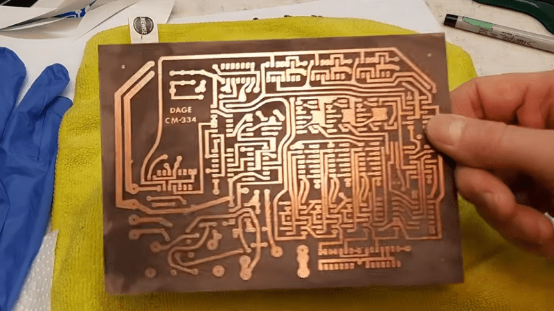
In the era before PCB shops would make almost any PCB imaginable, as well making many other manufacturing processes for prototypes available to hobbyists, there were several ways of making PCBs at home. Many of which involve harsh chemicals and were easy to mess up. Getting a single-layer PCB using the toner transfer method, for example, took a bit of practice (and a fume hood) to get right. [Bettina Neumryr] is working on a custom two-layer PCB, and has a new trick to get it to come out right despite the added complexity of the second layer.
The method starts out as a standard single-layer board in effect. Toner is ironed onto a copper board, in this case using a laminator, which allows the board to go into an acid bath which washes away all of the un-tonered copper. But with the second layer exposed, this would wash away the other side of the board completely. [Bettina] is using a new method here to protect that layer during the first bath: covering it in ink from a magic marker. With the first board etched, the ink and toner get washed off and the second layer is carefully lined up, put through the laminator, and then the opposite side gets covered in ink for the second acid bath.
After the process is complete and many layers of ink and toner are removed, [Bettina] is left with a PCB that’s ready to receive electronic components, if a little stained from all the ink. As to what this specific board is going to be used for, she’s kept that a bit cryptic as it’s the subject of a future video. Her builds usually revolve around designs from antique elecronics magazines, so it’s almost certainly something of that nature, and that’s also why this specific design couldn’t be just sent off to a board shop.





Lololol twice the work and the end result is still just a crappy etched PCB without soldermask or vias.
When you generate a stencil from KiCAD, EAGLE, Altium or whatever, open it in Inkscape or Adobe Illustrator and add very fine registration marks (something like 0,25pt).
Looking through some strong light you can now align both printouts, glue them together and sandwich copper board between them for toner transfer.
Yes, very odd indeed.
Yes, except you forgot one crucial part – the thickness of the board. If you just glue the sheets together on the edge, and then slide the board in between, you end up shifting the pattern if the seam doesn’t end up equally between both sides.
Instead, you align the masks, place them on top of your board, tape them down, drill two small holes through the stack and then you can align them using the drill bit through the holes.
As for aligning the masks, I used to print both sides on the same sheet and fold it on itself.
I’ve done this myself. Much faster, and registration was usually as good as I could get with separate transfers.
Is there some compelling reason not to align and laminate toner to both sides before etching?
This is what i wonder as well
We used to print the masks on overhead film, the printed side with toner towards the PCB. Line up the films of the 2 sides then use tape to fixate them, slide in the pcb, clamp the films down and expose each side and then etch. For quick inhouse prototyping in the early 90’s the alternative was using those pesky rolls of thin tape or special black markers to cover the UV reactant, or waiting weeks for very expensive prototype boards from a limited selection of companies.
What was old is new again…
As my mother will attest from when I was a teenager, nail varnish works well too and comes with a dinky little brush for applying liberal amounts to large areas!
I always keep a bottle of it in the shop, lots of uses
Oh, wow. You did that too!
Here’s an example from 1973…
https://hackaday.com/2026/09/29/improved-double-sided-toner-transfer-method/
And other professional and amateur, obsolete and modern techniques…
https://entertaininghacks.wordpress.com/2020/07/22/prototyping-circuits-easy-cheap-fast-reliable-techniques/
I wonder if acrylic paint works too, for those who’s hobbies overlap that way. Especially because we know how to strip it with relatively benign household cleaners which should work even better on a flat surface.
Acrylic spraypaint works really well for this application (and for electro-etching Aluminum as well, you can laser-engrave what you want to etch).
Alos, applying pressure to a soaked foam film, instead of the bathing thing, doesn’ that work cleaner?
i always added a few small alignment holes to the transfer page. id print it out on paper, tape it and drill the alignment holes out with a fine drill bit. then i print it on a blue sheet. put fine needles through the alignment marks and place the board on top aligning the pins. i pre punch the holes on the top layer and align those to the pins. i then tape the edges down with masking tape and remove the pins. i place the board on an old mouse pad and use use a clothes iron. down force only do not slide it or your transfer will smear, so you have to do it in patches if the board is large. flip it and do the other side. its usually usable for through hole work. i dispatch with the fume hood (who wants to live forever) and use the vinegar etch method. though to be fair i think its now cheaper to have a pcb mill do it.
Exactly what I did over 10 y ago
My one and only experience with the toner transfer method involved double-sided PCBs… 12 years ago, so I could have physical copies of homebrew NES games. I printed six PCBs, etched four and two of them were decent enough to be usable (had little enough defects to be salvageable)
Note: costume lab coats aren’t as good as the real thing.
No need for a fume hood to etch circuits. Really not.
And this method is a far cry from an improvement, it’s a regression.
Just print both sides, align the paper sheets on the window with enough daylight behind, fix them together at the edges (tape, glue, tacker, whatever goes) then iron both sides and etch.
Far less tedious, and no alignment problem if you’re a tad careful.
we live in a world where people now are afraid to breathe natural air. so its no wonder people are afraid of a few fumes. i get more noxious compounds out of my hash pipe.
Like some others above, that doesn’t seem novel to me, in fact there is a simple way: either align the masks and sandwich the pcb, or transfer one side without etching, drill holes (typically mounting holes), use those holes to align mask on the other side, transfer this other side, then simply etch the whole board both sides. I can’t comprehend why she needs to etch one side at a time. Also black marker is not a new invention, we’d always use black marker to patch up any bits where the toner didn’t stick for some reason before etching.
Heck, I’ve seen simple PCBs done entirely with permanent markers. Sometimes traces and pads are drawn directly by hand. At other times, large areas of copper are inked and then have the ink scratched away to form the necessary features.
Sometimes going beyond a ‘brute force and ignorance approach’ is a waste of time and resources.
I use wide masking tape to protect the non-printed side (rather than a Sharpie).
Butt up as many runs as necessary leaving no gap between. Then tape over the seams to be sure.
Removal and cleanup is easier.
Wouldn’t it be easier to tape the side you don’t want to etch, instead of using a sharpie?
Tape is hard to get full coverage with, actually. I’ve used vinyl electrical tape for this, and inevitably some electrolyte gets under there and frosts the copper (even though that whole side of the board is unconnected). Polyimide masking tape, same idea, it’s pretty rigid stuff and the adhesive doesn’t quite seal around overlapped edges. It’s actually pretty tricky to get a fully water-tight seal around corners!
If you can [get a tight seal], it’s nice to be able to merely tape around a plastic sheet that covers the bulk of the board, rather than unrolling that much tape (or permanent marker!) just for one go.
(I use a bespoke electrolytic method to remove the bulk of the metal; the relatively high voltage drop in the bath (~3V) leaves enough gradient that unconnected metal can end up partially etched. Ferric chloride will be worse, as it only needs to seep into the area to do its work.)
FeCl3 mixed 1:1 with DOT3 brake fluid is an excellent way to damge car paint. Not that I’m suggesting anything illegal 😛
Hmm, I knew that only break fluid was enough for this form of art. Sure, FeCl3 will help eating away the metal under the paint, so will might improve air flow by creating dimples (the metal sheet is thick enough to not be eaten through by FeCl3). If you have time and enough masking stuff, you can leave love messages embedded on the hood.
“I wrote you this message on your car’s hood to make you remember my feelings for you while it’s raining and the engine rusts away. Love, grandma”.
If you need a fume hood, you’re doing it … wrong.
I’ve etched plenty of PCBs using heated FeCl3 in a utility room. Just be sure to clean up any drips before they stain fabric or eat holes through your stainless steel sink.
Desde Argentina leyendo ésto! Hago PCB con la plancha de la ropa y toner desde el 2004, y llegue a hacer en doble faz, y las hice a ambas caras a la vez sin problemas. Simplemente dejaba unas marcas en las esquinas del papel alineaba y listo. Uso FeCl3 caliente a 45°C y se hacen rápido, puedo acelerar con algo de agua O3. Saludos.
I, like many others, used to make my own PCBs at home. If doing toner transfer, registration/fiducials are easy to add and really help with alignment.
Sharpie/magic marker has long been known as a “resist” (that’s what we used to call the stuff that protects your copper from the etchant).
I actually recall buying a PCB etching kit from radio shack in the late 90s that was literally a piece of copper clad, bottle of FeCl, and a sharpie.
I’m deeply confused by this video. My conclusion is that it’s some kind of rage/engage-bait. Good job, I certainly couldn’t resist.
Add some sharpie!
Consulting The Oracle, we can learn:
The DAGE CM-334 is an older, vintage electronic kit design used to build a capacitance meter.