Hack Allows ESP-01 To Go To Deep Sleep

The ESP-01 module based on the ESP8266 is all the rage with IoT folks at the moment – and why not. For about 5 bucks, it can’t be beat on price for the features it offers. The one thing that such radios do a lot is suck power. So, it’s no surprise that ways to cut down on the juice that this device consumes is top priority for many people. [Tim] figured out a simple hardware hack to get the ESP-01 to go to deep sleep, effectively reducing its current draw to 78uA – low enough to allow battery powered deployment.

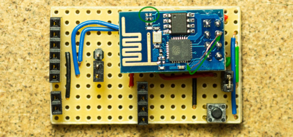
While [Tim] was working on understanding the ESP8266 tool chain (NodeMCU firmware > Lua interpreter > ESPlorer IDE), he realized that some essential pins weren’t accessible on the ESP-01 module. [Tim] built a Dev board on perf board that let him access these pins and also added some frills while at it. We’re guessing he (or someone else) will come up with a proper PCB to make things easier. But the real hack is on the ESP-01 module itself. [Tim] needed to hardwire the ‘post-sleep-reset-pin’ on the MCU to the Reset terminal. That, and also pry off the indicator LED’s with a screw driver! That sounds a bit drastic, and we’d recommend pulling out your soldering iron instead. If you’re one of the unlucky one’s to receive the “magic smoke” releasing ESP8266 modules, then you don’t need the LED anyway.

Watt Meter Build Walks You Through Power Measurement Basics

You almost never hear of a DC Watt Meter – one just does some mental math with Volts and Amps at the back of one’s head. An AC Watt Meter, on the other hand, can by pretty useful on any workbench. This handy DIY Digital AC Watt Meter not only has an impressive 30A current range, but is designed in a hand-held form factor, making it easy to carry around.

The design from Electro-Labs provides build instructions for the hardware, as well as the software for the PIC micro-controller at its heart. A detailed description walks you through the schematic’s various blocks, and there’s also some basics of AC power measurement thrown in for good measure. The schematic and board layout are done using SolaPCB – a Windows only free EDA tool which we haven’t heard about until now. A full BoM and the PIC code round off the build. On the hardware side, the unit uses MCP3202 12 bit ADC converters with SPI interface, making it easy to hook them up to the micro-controller. A simple resistive divider for voltage and an ACS-712  Hall Effect-Based Linear Current Sensor IC are the main sense elements. Phase calculations are done by the micro-controller. The importance of isolation is not overlooked, using opto-isolators to keep the digital section away from the analog. The board outline looks like it has been designed to fit some off-the-shelf hand-held plastic enclosure (if you can’t find one, whip one up from a 3D printer).

Although the design is for 230V~250V range, it can easily be modified for 110V use by changing a few parts. Swap the transformer, change the Resistive voltage divider values, maybe some DC level shifting, and you’re good to go. The one feature that would be a nice upgrade to this meter would be Energy measurements, besides just Power. For an inside look at how traditional energy meters work, head over to this video where [Ben Krasnow] explains KiloWatt Hour Meters