The Farnsworth Fusor is a fascinating device, a reactor that fuses hydrogen into helium by creating a plasma under a very high voltage. Although it isn’t a practical way to generate energy, it is a fascinating way to see nuclear fusion. An increasing number of home experimenters are starting to build their own fusors, and [Erik] decided he wanted to be among them. He’s put together a great build log of his progress, starting with a propane tank he bought off craigslist. He added a window, a vacuum pump and a 40KV power supply. Once he added some deuterium (electrolyzed from heavy water he bought from United Nuclear) it was ready to go. After a couple of failed runs, he got the characteristic plasma glow that shows that the reactor is working. The central globe is the plasma, while the light on the left side is a beam of electrons freed by the fusion process. So far, [Erik] has not detected the high-energy neutrons that would show that fusion is underway, but he is close.
Needless to say, this is not a casual build. [Erik] is using a 40KV power supply that would kill you in a heartbeat if your body happened to be the easiest pathway to ground, especially as the power supply is generating pulls over 9 amps to create the fusion reaction. [Erik] joins a select group of amateur fusor builders called the Plasma Club. It isn’t the first Farnsworth Fusor that we have covered, but it is one of the most impressive.
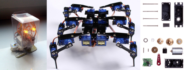
How do you make things move? You add in a motor that converts electrical energy into motion. That’s a simple idea, but how do you know where the motor is? That’s where the servo motor comes in. By adding a sensor and a controller to the mechanism, these motors can figure out how far they have rotated and maintain that setting without any need for external control.
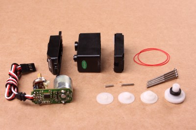
A disassembled servo motor showing the controller, motor, rotary encoder and gears. By oomlout, CC BY-SA 2.0
What is a Servo Motor?
These neat devices can be large or small, but they all share the same basic characteristics: a motor connected to a gearing mechanism and an encoder that detects the movement and speed of the motor. This combination means that the controlling device doesn’t need to know anything about the motor itself: the controller on the servo motor handles the process of feeding the appropriate power to the motor until it reaches the requested position. This makes it much easier to build things with servomotors, as the designer has already done all the hard work for you.
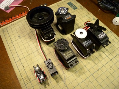
The first place that most people encounter a servo motor is in the small hobby servos that are used in remote control vehicles. Manufactured by companies like Hitec and Futaba, these drive a gear or arm that transfers the rotation of the motor to perform tasks like turning a wheel to steer a car, moving a control surface on an RC plane, or any task that requires a small range of motion at high precision. The gearing in the servomotor offers more torque than connecting the shaft directly to the motor. Most hobby servos of this type are restricted to a certain range of motion (usually 180 degrees) because the position encoder is a simple potentiometer connected to the output shaft.
A selection of different sized servo motors. By Osamu Iwasaki
Servomotors usually have three connection wires: a power line, a ground line and a signal line. The signal line is fed a pulse width modulation (PWM) signal that determines the angle that the servomotor moves to. As the name suggests, the length of the pulse (or the width, if you look at it on an oscilloscope) is the thing that controls the angle that the servo moves to: a short pulse (1 millisecond) sets it to the zero angle, while a long pulse of 2 milliseconds sets it to the maximum angle. A pulse length between these two limits signals the servomotor to move to the corresponding angle: 1.5 ms would set it to 90 degrees.
It is important to note that servomotors and stepper motors are not the same thing. Both are used for positioning, but steppers usually run without feedback. Instead, steppers turn (as the name suggest) in discrete steps. To figure out where a stepper motor is requires a limit switch, then driving the stepper until this is triggered. Then if you keep count out the number of steps that it’s traveled, you know where it is. That’s why devices like inkjet or 3D printers will move to their limits when they start up, so the controller can detect the far limit of the mechanism being driven, and calculate the current position from that.
How Do You Use A Servomotor?
Because the designers of servomotors have done most of the hard work for you, servomotors are very easy to use. To drive them, you just need to feed them power (usually 5V) and feed the PWM signal to the servomotor. You can drive them directly from an Arduino or similar microcontroller using a library that converts an angle into a PWM signal on one of the output pins.
Each servomotor requires a dedicated output pin if they are being driven this way, though, so if you are driving a lot of servomotors, a dedicated controller makes more sense. Devices such as the Adafruit Servo Shield and the Pololu Maestro allow you to control multiple servos from a single output pin on the microcontroller: the microcontroller sends a signal to the device addressing each servo in turn, and the device converts this into the PWM signals for each. If you need to drive a lot of servos, the SD84 can control up to 84 servos at once from a single USB port.
Got aliens in your attic? Squirrels in the skirting board? You need a trap, and [John Mangan] has come up with an interesting way to let you know that you have caught that pesky varmint: the IoT Critter Twitter Trap. By adding a ball switch, Electric Imp and a couple of batteries to a trap, he was able to set the trap to notify him when it caught something over Twitter. To do this, he programmed the Electric Imp to send a message over when a varmint trods on the panel inside the trap, slamming its door shut. The whole thing cost him less than $60 and can be seen in action after the break.
This is a pretty neat hack. I used to help with a Feral Fix program, where feral cats would be trapped, neutered and returned to the wild. This involved baiting the trap, then waiting hours in the cold nearby for the ferals to get comfortable enough to climb inside and trigger the trap. [John’s] version would only work indoors (as it uses WiFi), but it wouldn’t be that difficult to add a cell phone dongle or other RF solution to extend the range. With this hack, I could have at least waited somewhere warmer, while the trap would ping me when it was triggered.
If two is better than one, what about five? [Omnicrash] has posted a nice analysis of his monitor setup, which uses 5 portrait mounted monitors side-by-side. To minimize the bezel size between them, he removed the casing and built a custom stand that placed them all closely together for a surround viewing approach. He’s been using this setup for a couple of years and has posted a nice analysis of making it work for multiple purposes. On the upside, he says it is awesome for gaming and watching videos.
On the downside, NVidia’s drivers and multi-monitor setup are a pain, and some tasks just didn’t work with the bezels. He couldn’t, for instance, run a standard-sized remote desktop screen anywhere without having the bezel get in the way. So, with large, hi-res monitors now getting cheaper, would he do it again? “If I had to do it all over again nowadays however I’d probably just go with a single 34″ ultra-wide for about the same price..though I probably wouldn’t be able to help myself and would eventually be adding at least one on top and 2 in portrait on the side.”
I’ve been testing out the Raspberry Pi 3, and one thing I have found is that the WiFi antenna that was added in this new model is not especially good: the Pi has trouble connecting to my WiFi network in places that other devices have no issues. That’s not surprising, because the antenna on the Pi 3 is tiny: mounted right next to the display connector, it is just a few millimeters wide. [Ward] at DorkbotPDX agrees, so he decided to look into adding a better antenna by adding an external connector.
He tried two approaches: replacing the antenna with a tail connector, and adding a U.FL connector to the unused solder pads on the board. Both require some delicate soldering work, so they aren’t approached lightly. Replacing the antenna with an external connector produced a significant increase in signal output, which should equate with more range for the WiFi connection.
It is also interesting to note that the Pi 3 has solder pads on the board to add an external antenna connector, but that they are not used. Plus, one of the solder pads is covered by solder mask. Using these is the second approach that [Ward] used, soldering on a U.FL connector and connecting that to a small rubber duckie antenna. Again, this proved more efficient, increasing the power output of the antenna significantly.
NOTE: This hack definitely falls into “Don’t try this at home” territory. Messing with antennas voids the warranty and FCC certification for the Pi, and can cause all sorts of signal-related unpleasantness if you aren’t careful.
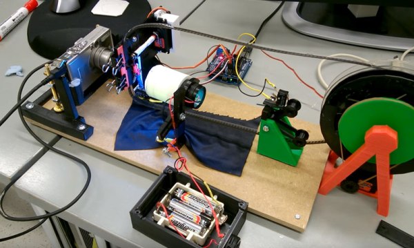
The 8mm film look is making a comeback, but distributing it is an issue. [Heikki Hietala] wanted an easy way to digitally capture the 8mm movies he made. So, he built an 8mm digitizer from an Arduino, a cheap Canon camera and the guts of an old 8mm film camera. When you throw in a few 3D printed components and some odd electronics, you get an impressive build that captures 8mm film with impressive speed and quality.
This build started with a Canon Ixus 5 camera running CHDK (the Canon Hack Development Kit) to lock the settings down. This points at the film strip through a macro lens so each frame of the strip fills the frame. An Arduino then triggers the camera to take a photo using a USB cable. The same Arduino also controls a motor that winds the film and triggers the film gate from the camera that he salvaged. By reversing the function and triggering it with a servo motor, he can easily blank off the edges of the frame so no stray light shining through the film material causes any problems. Once the camera has captured every frame on the strip, he feeds the captured images into Blender, which processes them and spits out the final movie.
This is a very impressive build overall. [Heikki] has obviously put a lot of thought into it, and the whole thing looks like it runs very efficiently and quickly. The captured video looks great, as you can see from this sample. The decision to use a salvaged film gate was a smart one: there is no point in reinventing the wheel if engineers of previous generations have solved the problem. Kudos to [Heikki] for also documenting the process in a lot of detail: he has produced a 5-part series on his blog that shows how and why he made the decisions he did. This series goes over the overall view of the project, using CHDK to control the camera, 3D printing parts, wiring the Arduino and writing the code that controls the system.
This sits nicely alongside the 8mm to video camera hack that we wrote about recently. This one doesn’t involve taking apart the camera (except for the sacrificial one that supplied the gate), and you still get that wonderfully grainy, jumpy look of 8mm film.
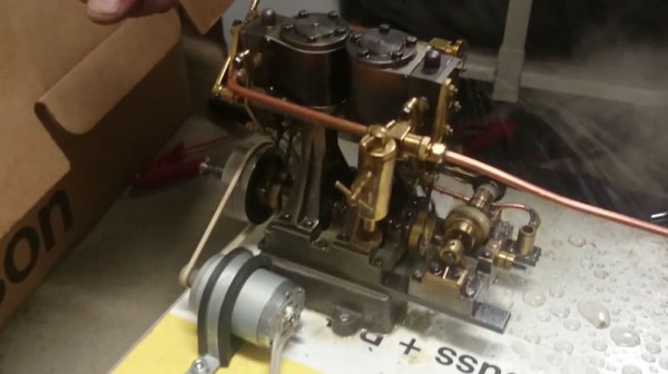
Steampunk usually involves sticking a few old valves on your laptop and riding a penny farthing, but [Alexzpro] understands the real thing: he just created a steam powered Raspberry Pi Zero (translated).
His setup is a little lashed together, but works it’s a throwback to electricity generation of old and deserves the steampunk moniker. A steam boiler drives a steam turbine, which turns a motor, generating electrical power. This feeds into a regulator and a bank of capacitors that smooths the voltage out to a nice even 5 Volts, which powers the Pi.
It’s not exactly efficient, but running the steam boiler using two propane blowtorches sure makes us grin. Usually we see people trying to go the opposite direction and power their projects with renewables. We can appreciate this for what it is too, and it’s certainly not the first time we’ve see a Raspberry Pi burning through electricity for little apparent gain.