You can go to any dollar store, gas station, big box store, or your favorite Internet retailer and get a USB power bank. It’s a lithium battery mashed into a plastic enclosure with a USB port, probably poorly engineered, but it does serve as a great power supply for the Raspberry Pi. For the Raspberry Pi Zero contest we’re running over on hackaday.io, [Patrick] built a lithium phosphate battery pack that’s much better engineered and has some features a simple USB power bank will never have.
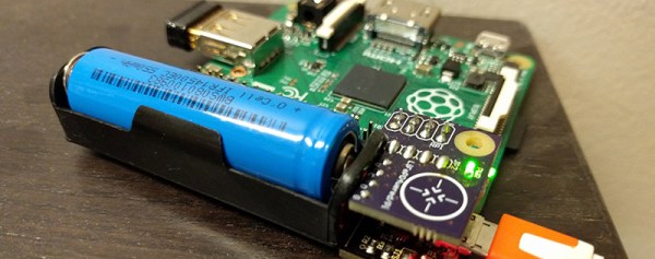
[Patrick]’s Raspberry Pi UPS isn’t just a battery and charge controller attached to the power rails; this board has a microcontroller that has full control over when the Pi wakes up, when the Pi goes to sleep, and can put the Pi into a clean shutdown, even in headless mode. SD cards around the world rejoiced.
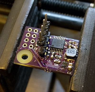
The electronics for this project are just a low-power MSP430 microcontroller and a boost regulator. The battery pack/power manager attaches to the Pi through the first few GPIO pins on the Pi’s 40-pin header. That’s enough to tap into the 3.3 and 5V supplies, along with the serial console so power events can be scripted on the Pi.
So far, [Patrick] has made a few time-lapse movies with his lithium battery backup, a Pi Model A+, and a Raspberry Pi camera. He managed to take 99 pictures over the course of about 24 hours, powered only by a single lithium-ion cell. You can check that video out below.
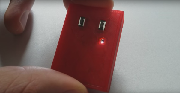
If you’re serious about your tea, you know that the line between a perfect brew and over-steeped dreck is a fine one. Seconds can make a difference, and for the tinkering tea drinker, this might lead you to build a tiny timer with just the features it needs to achieve tea perfection.
The circuit that tea-loving [acidbourbon] came up with for his timer is simplicity itself. It’s just an ATtiny25, an LED, two pushbutton switches and a piezo buzzer on one side of the PCB, with a coin battery on the flip side. The battery holder is an interesting design – a couple of rows of pin headers and a bit of springy metal. The user interface is as simple as the circuit – the buttons increment the time either one or ten minutes. The timer starts right away, the LED heartbeat counts down the seconds, and a distinctly British tune announces when it’s time for tea.
One possible improvement might be to have the LED flash the number of minutes remaining rather than just a single pulse heartbeat. That would be good feedback that you entered the right time in the first place. Other than that, it’s small enough to be handy, does just one job, and does it well – sounds like good design to us. Of course, if you want to complicate it a bit, you could always automate the tea steeping process.
If you’ve worked with steel or iron, you will be very familiar with rust. You will have an impressive armoury of wire brushes and chemicals to deal with it, and your sandblasting guy is probably in your speed-dial list.
We’ve had more than one Hackaday reader contact us of late with videos showing an apparently miraculous handheld laser unit effortlessly stripping away rust, and leaving a near-perfect surface with little mess. Can it be real, they ask, is it an internet hoax? After all if you have done battle with the dreaded iron oxide you’ll know there is no miracle fix to the problem, however you deal with it there has traditionally been hard work involved.
So after a bit of research, we find CleanLaser, the German company whose products feature in the videos. Quoting their website: “Powerful, very short, rapid and moving laser pulses produce micro-plasma bursts, shockwaves and thermal pressure resulting in sublimation and ejection of the target material”. So yes, it seems they’re real.
The website is at pains to stress the environmental benefits of the devices over comparable sandblasting or similar technologies, but has very little information on their safety. They are available in power ratings from 12W to 1KW which is a hell of a lot of laser power to be projecting, yet the operators seem only to be wearing goggles. Perhaps this comes back to the “Powerful, very short, rapid and moving” bit in the quote above, is there no point source to sear your retina? Laser experts please enlighten us in the comments.
If you work with metal or grew up in a metalworking business, this machine probably has you salivating. Sadly for hackers and makers though it’s probable that it and ones like it will be out of our price range for quite some time. Still, the prospect of a guy with one in an industrial unit appearing in most towns can’t be too far away, and that can only be a good thing
The video shows the machine in action. Rusty fire-grate in, perfect shiny surface out. Perhaps only those of you who have spent many hours with a wire brush will understand.
Steampunk usually involves sticking a few old valves on your laptop and riding a penny farthing, but [Alexzpro] understands the real thing: he just created a steam powered Raspberry Pi Zero (translated).
His setup is a little lashed together, but works it’s a throwback to electricity generation of old and deserves the steampunk moniker. A steam boiler drives a steam turbine, which turns a motor, generating electrical power. This feeds into a regulator and a bank of capacitors that smooths the voltage out to a nice even 5 Volts, which powers the Pi.
It’s not exactly efficient, but running the steam boiler using two propane blowtorches sure makes us grin. Usually we see people trying to go the opposite direction and power their projects with renewables. We can appreciate this for what it is too, and it’s certainly not the first time we’ve see a Raspberry Pi burning through electricity for little apparent gain.
If you are lucky enough to encounter a piece of homebrew electronics from the 1950s, the chances are that under the covers the components will be assembled on solder tags, each component with long leads, and chassis-mounted sockets for tubes. Easy to assemble with the most agricultural of soldering irons.
Open up a home build from the 1960s or early 1970s, and you might find the same passive components alongside germanium transistors mounted through holes in a curious widely spaced stripboard or even a home-made PCB with chunky wide tracks.
Solder tags aplenty in a commercial transmitter from the early 1960s
Cutting-edge 1970s homebrew
By the late 1970s and early 1980s you would find a more familiar sight. Dual-in-line ICs through-hole on 0.1″ spaced stripboard, and home-made PCBs starting to appear on fibreglass board. Easy to use, easy to solder. Familiar. Safe. Exactly what you’ll see on your breadboard nearly forty years later, and still what you’ll see from a lot of kit manufacturers.
But we all know that progress in the world of electronic components has not stood still. Surface-mount components have a history going back to the 1960s, and started to appear in consumer equipment from the end of the 1980s. More components per square inch, smaller, cheaper devices. Nowadays they are ubiquitous, and increasingly these new components are not offered in through-hole versions. Not a problem if your experiments are limited to the 741 and the 555, but something that rather cramps your style if your tastes extend to novel sensors for a microcontroller, or RF work.
This development has elicited a range of reactions. Many people have embraced the newer medium with pleasure, and the Hackaday.io project pages are full of really clever SMD projects as a result. But a significant number have not been able to make the jump to SMD, maybe they are put off by the smaller size of SMD components, the special tools they might require, or even the new skills they’d have to learn. When you sell a kit with SMD components these are the reactions you will hear from people who like the kit but wish it was available in through-hole, so this article is for them. To demystify working with SMDs, and to demonstrate that SMD work should be within the grasp of almost anyone who can wield a soldering iron.
But They’re So Tiny!
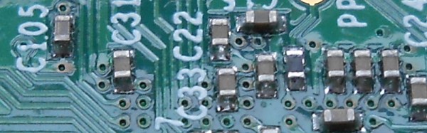
Tiny SMDs – fortunately most of which you will not have to worry about.
It’s likely to be the first reaction from a lifelong through-hole solderer. SMD parts are often very small indeed, and even those with larger packages can have leads that seem as numerous and thin as the hairs on a cat when seen with the rabbit-in-the-headlights panic of the uninitiated.
But it is important to take a step back and understand that not all SMDs are created equal. Some of them are grain-of-sand tiny and only hand-solderable by those with God-like powers, but plenty of devices are available in SMD packages large enough for mere mortals.
So don’t worry when you look at a board covered with grain-of-dust-sized components. Very few people could attempt that level of construction, your scribe certainly can’t. (We await commenters claiming to routinely hand-solder thousand-pin BGAs and 01005 chip components with anticipation, however such claims are useless without proof.)
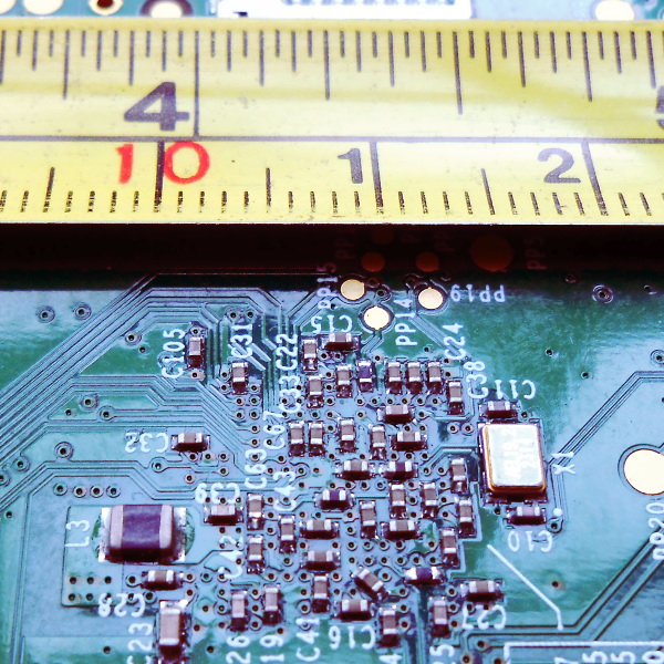
Instead, concentrate on the SMD packages you can handle. SMD chip component packages are refered to by a number that relates to their dimension. Confusingly there are both metric and imperial versions of the scheme, but the format is the same: length followed by width.
Consider the picture above with the PCB and the tape measure, it’s the underside of a Raspberry Pi model B+, and will have been assembled by a robotic pick-and-place machine. The majority of the components are very tiny indeed, but you will notice L3 as the black component towards the bottom left that looks huge compared to its neighbours. That package is a “1008”, 0.1 inches long by 0.08 inches wide. It’s still tiny, but imagine picking it up with a pair of tweezers under a magnifying glass. Not so bad, is it. You’ve probably handled plenty of things in that size range before, do SMD parts seem so scary now? The larger components – 0805, 1008, and 1206 – are surprisingly within the grasp of the average maker.
But I need all sorts of special tools!
Retro Populator, a homebrew pick-and-place machine we featured back in 2014
In a commercial environment an SMD device will be assembled by machine. Glue or solder paste will be printed in the relevant parts of the board, and a robotic pick-and-place machine will retrieve components from their tape packaging and automatically place them in their correct orientations. The board will then be soldered all-at once, either in a reflow oven or by a wave soldering machine.
You’ll also see all manner of commercial kit aimed at the bench-top SMD constructor. Hot air soldering stations or SMD bits for conventional irons, all of which are very useful but come with a hefty price tag.
The good news is that you don’t need any of these special tools to dip your toe into the SMD water. You almost certainly already have everything you need, and if you don’t then very little of what you lack is specifically for SMD work. If you have the following items then you are good to go:
A basic SMD soldering toolkit
A good light source. Even the larger SMDs are still pretty small. Plenty of light ensures you will be able to see them clearly. A good downward pointing desk lamp should suffice. A clear high-contrast surface. Because SMDs can be difficult to see, it helps if they are manipulated over a bright white surface. A fresh sheet of white printer paper on a desk makes a suitable working area. Good hands-free magnification. Unless you are fortunate enough to have amazing eyesight, you will need a decent magnifier to work with surface-mount components. The “Helping hands” type on a stand are suitable. A very small flat-blade screwdriver. You will need this to hold surface-mount components down while you solder them. A good-quality set of precision metal tweezers. You will need these for picking up, manipulating, and turning over surface-mount devices. A fine-tipped soldering iron. If you have a standard fine tipped iron suitable for use with conventional 0.1” pitch through-hole components then you should be well-equipped.
That said there is one special tool that might be worth your consideration. Holding an SMD device while soldering it can sometimes seem like a task that needs three hands, so one or two tools can be found to help. Fortunately this is something you can build yourself. Take a look at the SMD Beak, a weighted arm for example, or your scribe’s spring clamp third hand.
I’m sorry, this is just beyond my soldering skill level
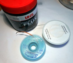
Desolder braid and plenty of flux are your friends.
It is easy to imagine when you are looking at an SMD integrated circuit that its pins are just too small and too close together, you couldn’t possibly solder them by hand. The answer is that of course you can, you simply need to view how you solder them in a different way.
With a through-hole IC you solder each 0.1″ pitch pin individually. It is something of a disaster if you manage to put a solder bridge between two pins, and you race for your desolder pump or braid.
With a surface-mount IC by comparison there is little chance that you as a mere mortal could solder each pin individually, so you don’t even try. Instead you solder an entire row at once with an excess of solder, and remove the resulting huge solder bridge with desolder braid to leave a very tidy and professional-looking job. Surface tension and plenty of flux are your friends, and there is very little soldering skill required that you do not already have if you are an experienced through-hole solderer.
If you can hold it down onto the board and see it clearly with your magnifier if necessary, then it doesn’t matter what the component is, you can solder it. Give it a try, you’ll surprise yourself!
What next?
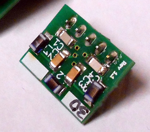
1206 chip discrete components hand-soldered to a PCB
So we hope we’ve convinced you as an SMD doubter, that you have the ability to work with SMDs yourself. What next?
But there is no substitute for practice. Find a scrap board populated with reasonably-sized surface-mount components, and have a go at reworking it. Desoldering its components may be a bit difficult, but you should easily be able to rework the solder joints. Slather an integrated circuit’s pins with flux, and try running a blob of molten solder along them, then removing the excess with desolder braid. The great thing about a scrap board is that it doesn’t matter if you damage it, so you can practice these techniques to your heart’s content until you are satisfied with your new-found skill.
So you’re ready to move forward, and make your first SMD project. Well done! What you do next is up to you. Design your own circuit and get a PCB made, buy a kit, or find an SMD project you like on Hackaday.io with downloadable PCB files and order your own.
Whatever you do, be happy that you’ve conquered your SMD fears, and resolve to be first in the queue to try any new technology in the future!
Well, if you’re not scared about the singularity yet, how about now? Stanford robotics just demonstrated six MicroTug (μTug) minibots — weighing 100g together — move an 1800kg sedan on polished concrete.
The research is being performed at Stanford’s Biomimetrics and Dextrous Manipulation Lab by [David L. Christensen] of the Engineering department — the car being pulled? His. The tests were performed to determine the effectiveness of robotic teamwork — mimicking the behaviors shown by ants.
The robots use an adhesive technique as found in gecko feet to adhere themselves to the concrete, and use micro-winches to tug the car. Individually each μTug minibot can pull 23kg. The strength to weight ratio of the hoard of minibots is 18,000:1!
I was visiting San Francisco, scratching my head for something cool to cover for Hackaday. When it hit me: this is one of the leading cities in the world for starting new companies. It’s known for its software, but with Tesla, Type A Machines, Intel, Apple, and more within an hour’s drive of the city, there’s got to be a hardware scene as well. Silicon isn’t a software product after-all. But where do you find it, and how do you get a hardware start-up going in one of the most expensive cities in the world?
That’s where hardware accelerators or incubators, whichever name they prefer, come in. One-third hackerspace, two-thirds business crash course, they help you skip a lot of the growing pains associated with starting a capital intensive thing like a hardware business. I dropped in, and they kindly gave me a few minutes of their time. I wanted to find out what a hacker could do if they felt it was time to turn those skulls into dollars. What are the requirements. What is the cost? What help does the incubator offer to the burgeoning capitalist in a hacker?
 [Patrick]’s Raspberry Pi UPS isn’t just a battery and charge controller attached to the power rails; this board has a microcontroller that has full control over when the Pi wakes up, when the Pi goes to sleep, and can put the Pi into a clean shutdown, even in headless mode. SD cards around the world rejoiced.