Simple STM32 Frequency Meter Handles Up To 30MHz With Ease

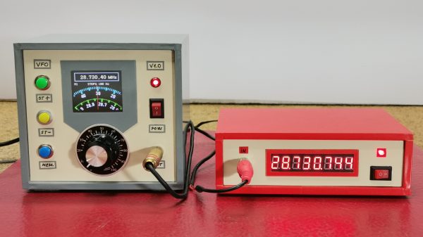
[mircemk] had previously built a frequency counter using an Arduino, with a useful range up to 6 MHz. Now, they’ve implemented a new design on a far more powerful STM32 chip that boosts the measurement range up to a full 30 MHz. That makes it a perfect tool for working with radios in the HF range.

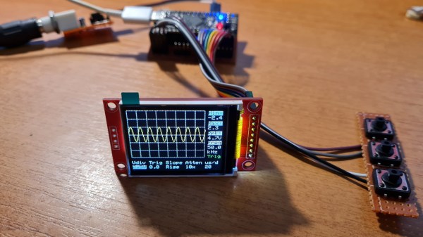
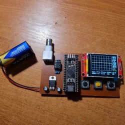
The project is relatively simple to construct, with an STM32F103C6 or C8 development board used as the brains of the operation. It’s paired with old-school LED 7-segment displays for showing the measured frequency. Just one capacitor is used as input circuitry for the microcontroller, which can accept signals from 0.5 to 3V in amplitude. [mircemk] notes that the circuit would be more versatile with a more advanced input circuit to allow it to work with a wider range of signals.

It’s probably not the most accurate frequency counter out there, and you’d probably want to calibrate it using a known-good frequency source once you’ve built it. Regardless, it’s a cheap way to get one on your desk, and a great way to learn about measuring and working with time-varying signals. You might like to take a look at the earlier build from [mircemk] for further inspiration. Video after the break.

Continue reading “Simple STM32 Frequency Meter Handles Up To 30MHz With Ease”

An LM386 Oscillator Thanks To Tungsten Under Glass

Once ubiquitous, the incandescent light bulb has become something of a lucerna non grata lately. Banned from home lighting, long gone from flashlights, and laughed out of existence by automotive engineers, you have to go a long way these days to find something that still uses a tungsten filament.

Strangely enough, this lamp-stabilized LM386 Wien bridge oscillator is one place where an incandescent bulb makes an appearance. The Wien bridge itself goes back to the 1890s when it was developed for impedance measurements, and its use in the feedback circuits of vacuum tube oscillators dates back to the 1930s. The incandescent bulb is used in the negative feedback path as an automatic gain control; the tungsten filament’s initial low resistance makes for high gain to kick off oscillation, after which it heats up and lowers the resistance to stabilize the oscillation.

For [Grug Huler], this was one of those “just for funsies” projects stemming from a data sheet example circuit showing a bulb-stabilized LM386 audio oscillator. He actually found it difficult to source the specified lamp — there’s that anti-tungsten bias again — but still managed to cobble together a working audio oscillator. The first pass actually came in pretty close to spec — 1.18 kHz compared to the predicted 1.07 kHz — and the scope showed a very nice-looking sine wave. We were honestly a bit surprised that the FFT analysis showed as many harmonics as it did, but all things considered, the oscillator performed pretty well, especially after a little more tweaking. And no, the light bulb never actually lights up.

Thanks to [Grug] for going down this particular rabbit hole and sharing what he learned. We love builds like this that unearth seemingly obsolete circuits and bring them back to life with modern components. OK, calling the LM386 a modern component might be stretching things a bit, but it is [Elliot]’s favorite chip for a reason.

Continue reading “An LM386 Oscillator Thanks To Tungsten Under Glass”

STM32 Oscilloscope Uses All The Features

[jgpeiro] is no slouch when it comes to building small, affordable oscilloscopes out of common microcontrollers. His most recent, based on an RP2040 with two channels that ran at 100 MSps, put it on the order of plenty of commercially-available oscilloscopes at this sample rate but at a fraction of the price. He wanted to improve on the design though, making a smaller unit with a greatly reduced bill-of-materials and with a more streamlined design, so he came up with this STM32-based oscilloscope.

The goal of this project was to base as many of the functions around the built-in capabilities of the STM32 as possible, so in addition to the four input channels and two output channels running at 1 MHz, the microcontroller also drives a TFT display which has been limited to 20 frames per second to save processor power for other tasks. The microcontroller also has a number of built-in operational amplifiers which are used as programmable gain amplifiers, further reducing the amount of support circuitry needed on the PCB while at the same time greatly improving the scope’s capabilities.

In fact, the only parts of consequence outside of the STM32, the power supply, and the screen are the inclusion of two operational amplifiers included to protect the input channels from overvoltage events. It’s an impressive build in a small form factor, and we’d say the design goal of keeping the parts count low has been met as well. If you do need something a little faster though, his RP2040-based oscilloscope is definitely worth checking out.

Continue reading “STM32 Oscilloscope Uses All The Features”

Blinkenlights To Bootloader: A Guide To STM32 Development

While things like the Arduino platform certainly opened up the gates of microcontroller programming to a much wider audience, it can also be limiting in some ways. The Arduino IDE, for example, abstracts away plenty of the underlying machinations of the hardware, and the vast amount of libraries can contribute to this effect as well. It’s not a problem if you just need a project to get up and running, in fact, that’s one of its greatest strengths. But for understanding the underlying hardware we’d recommend taking a look at something like this video series on the STM32 platform.

The series comes to us from [Francis Stokes] of Low Byte Productions who has produced eighteen videos for working with the STM32 Cortex-M4 microcontroller. The videos start by getting a developer environment up and blinking LEDs, and then move on to using peripherals for more complex tasks. The project then moves on to more advanced topics and divides into two parts, the development of an application and also a bootloader. The bootloader begins relatively simply, and then goes on to get more and more features built into it. It eventually can validate and update firmware, and includes cryptographic signing (although [Francis] notes that you probably shouldn’t use this feature for production).

One of the primary goals for [Francis], apart from the actual coding and development, was to liven up a subject matter that is often seen as dry, which we think was accomplished quite well. A number of future videos are planned as well. But, if you’re not convinced that the STM32 platform is the correct choice for you, we did publish a feature a while back outlining a few other choices that might provide some other options to consider.

Continue reading “Blinkenlights To Bootloader: A Guide To STM32 Development”

The completed oscilloscope in parts, with the screen in the front connected with prototyping wires, protoboarded buttons on the right, and the BlackPill board somewhere behind

DIY STM32 Scope Is Simple, Cheap, And Featureful

Would you like to have a small digital oscilloscope? Do you have a spare BlackPill (STM32F401) board and a TFT display laying around? [tvvlad1234] presents us with a simple and educational digital storage oscilloscope design that barely needs any components for you to build one, and it’s packed with features just like you would expect from a self-respecting open-source project. Not just that — it can even stream data to your computer, in a format compatible with the TekScope software!

The same scope design, but now on a self-etched board
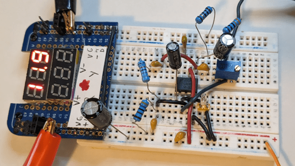
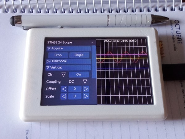
It’s hard to overshadow just how easy this scope is to build, use, and hack on. You really don’t need much in the way of parts, a protoboard will do, though you can also etch or order your own PCBs. The front-end is super straightforward to find components for and assemble, a few opamps and resistors is all you need. So after jumper-wiring the LCD and three push buttons to your BlackPill, you’re golden.

Of course, the simple frontend results in the input range being from -3.3 V to 3.3 V, but as you could guess, this is exactly the kind of project where you could tweak the resistors and even upgrade it later on. Are you a bit lost in how oscilloscopes work? [tvvlad1234] has an explainer for you, too!

This build could easily take up a honorary “temporary turned permanent” place on your bench, thanks to its McGyver-esque qualities. It’s also, quite possibly, a better scope than the red “soldering kit” ones we’ve seen online. All in all, it’s a strong contender in the “simple and powerful DIY scope” arena, before this, we’ve seen one built with an Arduino Nano, and one with a Pi Pico.

Dumping script window, showing the bytes being dumped one by one from the STM chip

Need To Dump A Protected STM32F0x? Use Your Pico!

Sometimes, security mechanisms can be bypassed if you just do things slightly out of the ordinary. For instance, readout protection on microcontrollers is a given nowadays, to the point where it’s intentionally enabled and relied upon as a major technical measure to protect intellectual property. The gist is — when you connect to a microcontroller over its debug interface and then ask to read its flash memory, it will politely refuse. However, [Racerxdl] shows us that in practice, it’s not flawless protection – for certain chips, you just need to be a little quicker than usual.

Usually, flashing and debugging software will chat with the microcontroller for a bit, and probe parameters before going for any direct requests. However, if you skip the courtesy and bluntly get to the point immediately right after power is applied to the microcontroller, you can intimidate them just enough to give you one byte of its memory before it refuses to cooperate further. Since that can be any byte you wish, you can read the entire flash — one byte at a time.

You need to power cycle the chip before you can progress, so the hardware does involve a bit more than just an SWD interface, and it will take a fair bit more time than reading out a non-protected chip the usual way; plus, of course, the debugging interface needs to be active for this in the first place, which isn’t always the case. However, it still beats paying a few thousand dollars for a factory in China to decap your chip and read it out using a fancy machine.

[Racerxdl] didn’t just write a proof-of-concept for this attack – they implemented it for one of our favourite chips, the RP2040. As such, you no longer need an unobtainium STM32 to dump an unobtainium STM32.

To be clear, [Racerxdl] didn’t design this attack — it’s been around for some time now. Credit for that goes to Johanes Obermaier. All in all, this is a wonderful reminder that seemingly reliable security mechanisms can be foiled by the simplest tricks. For instance, if your chip erases the flash when you unlock its protection, you can just tell it not to.

A EuroRack synthesizer module with an oscilloscope in the background showing a waveform

Recreating The Sounds Of The ’90s With A YM3812 Synthesizer

One reason the x86 PC became the dominant game platform in the early 1990s was the availability of affordable sound cards like the AdLib and Sound Blaster. These provided a quantum leap in sound quality compared to the PC speaker’s tinny beeps, thanks to Yamaha’s YM3812 chip, also known as OPL2. [Tyler] has made a detailed study of the various OPL series chips and wrote a comprehensive guide describing their operation.

[Tyler] begins by explaining the theory of FM synthesis. The basic idea is that you generate sine waves of different frequencies, combine them through mixing and modulation, and then adjust their strength over time. This way, a few simple operations on the chip’s nine sound channels can generate an astonishing variety of sounds from clear notes to chaotic noise. He then delves into the details of the YM3812 chip, including its 279 different register settings that enable all these operations.

The final goal of [Tyler]’s research is the design of a YM3812 EuroRack module that fits inside standard modular synthesizers. He’ll go into detail on the board’s design and construction in future blog posts, but he already shows the finished product and demonstrates its features in the video embedded below. It’s a great introduction if you’re new to FM synthesis and want to recreate those magic DOS game sounds.

Of course, you can also just connect the OPL2 chip to your DOS computer, whether through a classic sound card or through a parallel port. The related YM2612 from the Sega Genesis also makes a fine synthesizer.

Continue reading “Recreating The Sounds Of The ’90s With A YM3812 Synthesizer”