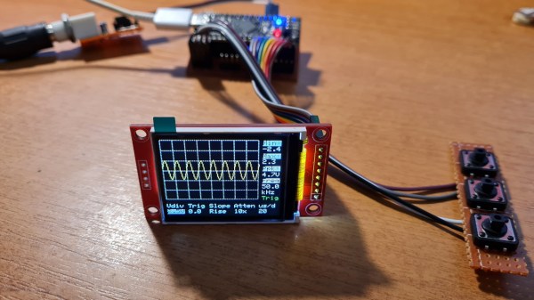
The completed oscilloscope in parts, with the screen in the front connected with prototyping wires, protoboarded buttons on the right, and the BlackPill board somewhere behind

DIY STM32 Scope Is Simple, Cheap, And Featureful

Would you like to have a small digital oscilloscope? Do you have a spare BlackPill (STM32F401) board and a TFT display laying around? [tvvlad1234] presents us with a simple and educational digital storage oscilloscope design that barely needs any components for you to build one, and it’s packed with features just like you would expect from a self-respecting open-source project. Not just that — it can even stream data to your computer, in a format compatible with the TekScope software!
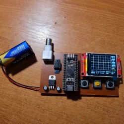
The same scope design, but now on a self-etched boardIt’s hard to overshadow just how easy this scope is to build, use, and hack on. You really don’t need much in the way of parts, a protoboard will do, though you can also etch or order your own PCBs. The front-end is super straightforward to find components for and assemble, a few opamps and resistors is all you need. So after jumper-wiring the LCD and three push buttons to your BlackPill, you’re golden.

Of course, the simple frontend results in the input range being from -3.3 V to 3.3 V, but as you could guess, this is exactly the kind of project where you could tweak the resistors and even upgrade it later on. Are you a bit lost in how oscilloscopes work? [tvvlad1234] has an explainer for you, too!

This build could easily take up a honorary “temporary turned permanent” place on your bench, thanks to its McGyver-esque qualities. It’s also, quite possibly, a better scope than the red “soldering kit” ones we’ve seen online. All in all, it’s a strong contender in the “simple and powerful DIY scope” arena, before this, we’ve seen one built with an Arduino Nano, and one with a Pi Pico.

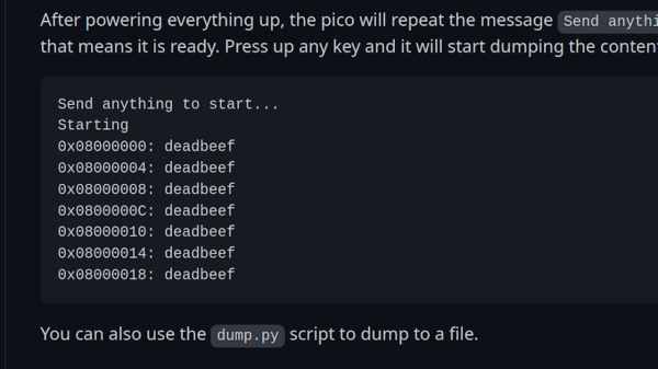
Dumping script window, showing the bytes being dumped one by one from the STM chip

Need To Dump A Protected STM32F0x? Use Your Pico!

Sometimes, security mechanisms can be bypassed if you just do things slightly out of the ordinary. For instance, readout protection on microcontrollers is a given nowadays, to the point where it’s intentionally enabled and relied upon as a major technical measure to protect intellectual property. The gist is — when you connect to a microcontroller over its debug interface and then ask to read its flash memory, it will politely refuse. However, [Racerxdl] shows us that in practice, it’s not flawless protection – for certain chips, you just need to be a little quicker than usual.

Usually, flashing and debugging software will chat with the microcontroller for a bit, and probe parameters before going for any direct requests. However, if you skip the courtesy and bluntly get to the point immediately right after power is applied to the microcontroller, you can intimidate them just enough to give you one byte of its memory before it refuses to cooperate further. Since that can be any byte you wish, you can read the entire flash — one byte at a time.

You need to power cycle the chip before you can progress, so the hardware does involve a bit more than just an SWD interface, and it will take a fair bit more time than reading out a non-protected chip the usual way; plus, of course, the debugging interface needs to be active for this in the first place, which isn’t always the case. However, it still beats paying a few thousand dollars for a factory in China to decap your chip and read it out using a fancy machine.

[Racerxdl] didn’t just write a proof-of-concept for this attack – they implemented it for one of our favourite chips, the RP2040. As such, you no longer need an unobtainium STM32 to dump an unobtainium STM32.

To be clear, [Racerxdl] didn’t design this attack — it’s been around for some time now. Credit for that goes to Johanes Obermaier. All in all, this is a wonderful reminder that seemingly reliable security mechanisms can be foiled by the simplest tricks. For instance, if your chip erases the flash when you unlock its protection, you can just tell it not to.

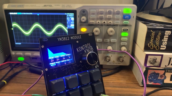
A EuroRack synthesizer module with an oscilloscope in the background showing a waveform

Recreating The Sounds Of The ’90s With A YM3812 Synthesizer

One reason the x86 PC became the dominant game platform in the early 1990s was the availability of affordable sound cards like the AdLib and Sound Blaster. These provided a quantum leap in sound quality compared to the PC speaker’s tinny beeps, thanks to Yamaha’s YM3812 chip, also known as OPL2. [Tyler] has made a detailed study of the various OPL series chips and wrote a comprehensive guide describing their operation.

[Tyler] begins by explaining the theory of FM synthesis. The basic idea is that you generate sine waves of different frequencies, combine them through mixing and modulation, and then adjust their strength over time. This way, a few simple operations on the chip’s nine sound channels can generate an astonishing variety of sounds from clear notes to chaotic noise. He then delves into the details of the YM3812 chip, including its 279 different register settings that enable all these operations.

The final goal of [Tyler]’s research is the design of a YM3812 EuroRack module that fits inside standard modular synthesizers. He’ll go into detail on the board’s design and construction in future blog posts, but he already shows the finished product and demonstrates its features in the video embedded below. It’s a great introduction if you’re new to FM synthesis and want to recreate those magic DOS game sounds.

Of course, you can also just connect the OPL2 chip to your DOS computer, whether through a classic sound card or through a parallel port. The related YM2612 from the Sega Genesis also makes a fine synthesizer.

Continue reading “Recreating The Sounds Of The ’90s With A YM3812 Synthesizer”

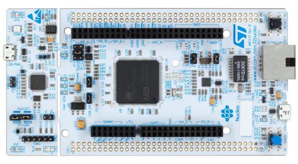
Nucleo-F429ZI development board with STM32F429 microcontroller

Epic Guide To Bare-Metal STM32 Programming

[Sergey Lyubka] put together this epic guide for bare-metal microcontroller programming.  While the general concepts should be applicable to most any microcontroller, [Sergey]s examples specifically relate to the Nucleo-F429ZI development board featuring the ARM-based STM32F429 microcontroller.

In the realm of computer systems, bare-metal programming most often refers to programming the processor without an intervening operating system. This generally applies to programming BIOS, hardware drivers, communication drivers, elements of the operating system, and so forth. Even in the world of embedded programming, were things are generally quite low-level (close to the metal), we’ve grown accustomed to a good amount of hardware abstraction. For example, we often start projects already standing on the shoulders of various libraries, boot loaders, and integrated development tools.

When we forego these abstractions and program directly on the microprocessor or microcontroller, we’re working on the bare metal. [Sergey] aptly defines this as programming the microcontroller “using just a compiler and a datasheet, nothing else.” His guide starts at the very foundation by examining the processor’s memory map and registers including locations for memory mapped I/O pins and other peripherals.

The guide walks us through writing up a minimal firmware program from boot vector to blinking an LED connected to an I/O pin. The demonstration continues with setup and use of necessary tools such as the compiler, linker, and flasher. We move on to increasingly advanced topics like timers, interrupts, UART output, debuggers, and even configuring an embedded web server to expose a complete device dashboard.

While initially more time consuming, working close to the metal provides a good deal of additional insight into, and control over, hardware operations.  For even more on the subject, you may like our STM32 Bootcamp series on bare-metal STM32 programming.

Bare-Metal STM32: Setting Up And Using SPI

The Serial Peripheral Interface (SPI) interface was initially standardized by Motorola in 1979 for short-distance communication in embedded systems. In its most common four-wire configuration, full-duplex data transfer is possible on the two data (MOSI, MISO) lines with data rates well exceeding 10 Mb/s. This makes SPI suitable for high-bandwidth, full-duplex applications like SD storage cards and large resolution, high-refresh displays.

STM32 devices come with a variable number of SPI peripherals, two in the F042 at 18 Mb/s and five in the F411. Across the STM32 families, the SPI peripheral is relatively similar, with fairly minor differences in the register layout. In this article we’ll look at configuring an SPI peripheral in master mode.

Continue reading “Bare-Metal STM32: Setting Up And Using SPI”

DIY LED Bulb Lacks Correct Lugs, So M3 Bolts To The Rescue

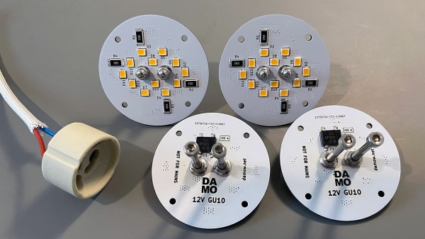
[Damo] has an interesting LED bulb project with a neat twist: he converted some outdoor lighting to 12 V LED lighting with some self-designed bulb replacements and decided to reuse the existing GU10 sockets and wiring. That meant putting GU10 lugs onto his custom PCBs, but he ran into a snag.

These GU10 bulb lugs are tough to buy in small quantities. Luckily, M3 socket head bolts are a near-perfect match.

Those distinctive lugs that twist into GU10 sockets? [Damo] simply couldn’t find anywhere offering to sell them in small quantities. So he did what any enterprising hacker would do and found a substitute that was both accessible and economical: M3 bolts. Apparently, socket-headed M3 bolts are pretty much identical in size to GU10 lugs. Who’d have thought?

[Damo]’s retrofit worked great, and thanks to M3 bolts he was able to re-use the existing weatherproof wiring and sockets in his yard. His design files are here on GitHub.

We do love using things for other than their intended purpose, but as [Damo] points out, GU10 sockets are normally connected to mains power. So if you decide to use his design (or use GU10 sockets for your own purposes), be aware that you’ll have hardware that looks interchangeable with other (mains-connected) sockets, but isn’t. Be mindful of that, and take appropriate precautions. Avoiding electrical oopsies is always worth putting effort into, after all.

Bare-Metal STM32: Adding An Analog Touch With ADCs

An Analogue to Digital Converter (ADC) is at its core a straight-forward device: by measuring an analog voltage within a set range and converting the measured level to a digital value we can use this measurement value in our code. Through the use of embedded ADCs in microcontrollers we can address many essential use cases, ranging from measuring the setting on a potentiometer, to reading an analog output line on sensors, including the MCU’s internal temperature and voltage sensors.

The ADCs found in STM32 MCUs have a resolution between 12 to 16 bits, with the former being the most common type. An ADC can be configured to reduce this resolution, set a specific sampling speed, and set up a multi-mode configuration depending on the exact ADC peripheral. STM32 MCUs feature at least a single ADC peripheral, while some have multiple. In this article we will take a look at how to configure and use the basic features of the ADCs in STM32 MCUs, specifically the ADCs found in F0 and the ADC5_V1_1 type as found in most F3-family MCUs.

Continue reading “Bare-Metal STM32: Adding An Analog Touch With ADCs”