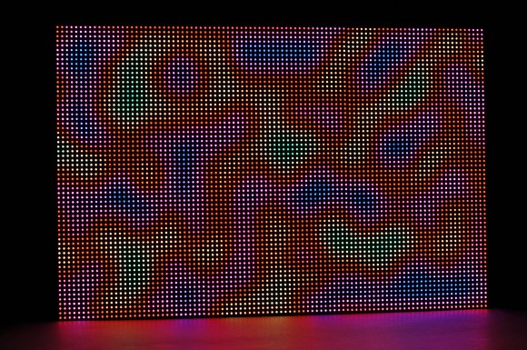
This is 6,144 RGB LEDs being controlled by a BeagleBone Black and a FPGA. This gives the display 12 bit color and a refresh rate of 200 Hz. [Glen]’s 6 panel LED wall uses the BeagleBone Black to generate the image, and the LogiBone FPGA board for high speed IO.
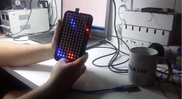
[Glen] started off with a single 32 x 32 RGB LED panel, and wrote a detailed tutorial on how that build works. The LED panels used for this project have built in drivers, but they cannot do PWM. To control color, the entire panel must be updated at high speed.
The BeagleBone’s IO isn’t fast enough for this, so a Xilinx Spartan 6 LX9 FPGA takes care of the high speed signaling. The image is loaded into the FPGA’s Block RAM by the BeagleBone, and the FPGA takes care of the rest. The LogiBone maps the FPGA’s address space into the CPU’s address space, which allows for high speed transfers.
If you want to drive this many LEDs, you’ll need to look beyond the Arduino. [Glen]’s work provides a great starting point, and all of the source is available on Github.
[Thanks to Jonathan for the tip]