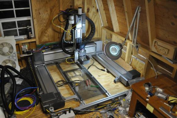
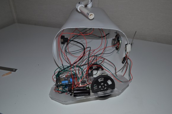
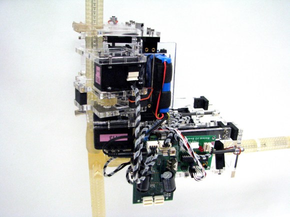
Building A Strandbeest

flexing-jansen-mechanism

[Jeremy] may have given up on his big hexapod project, but that doesn’t mean he’s out of the world of legged robots just yet. He’s embarked on another project, much more elegant and beautiful than a simple hexapod. This time, he’s building a Strandbeest, the same machine designed by walking machine extraordinaire [Theo Jansen].

Coming up with the correct lengths and joints of a Strandbeest leg linkage isn’t something you can just pull out of your head, so after [Jeremy] found the inspiration for his new project he dug into the related literature on Strandbeest legs. He found the work of [Dominique Studer] and set to work making his own mechanical legs.

Right now, [Jeremy] has a prototype of the Strandbeest leg linkage made out of wood. It still needs a little bit of work, but soon enough there will be a PVC pipe Mountainbeest trolling the backwoods near [Jeremy]’s house.

Continue reading “Building A Strandbeest”

Omniwheel Robot Build Uses A Bit Of Everything

Machinist, electronics engineer, programmer, and factory worker are all skills you can wield if you take on a project like building this omniwheel robot (translated).

The omniwheels work in this tripod orientation because they include rollers which turn perpendicular to the wheel’s axis. This avoids the differential issue cause by fixed-position wheels. When the three motors are driven correctly, as shown in the video below, this design makes for the most maneuverable of wheeled robots.

An aluminum plate serves as the chassis. [Malte] milled the plate, cutting out slots for the motor with threaded holes to receive the mounting screws. A few stand-offs hold the hunk of protoboard which makes up the electronic side of the build. The large DIP chip is an ATmega168. It drives the motors via the trio of red stepper motor driver boards which he picked up on eBay.

So far the vehicle is tethered, using a knock-off of a SixAxis style controller. But as we said before, driving the motors correctly is the hard part and he’s definitely solved that problem.

Continue reading “Omniwheel Robot Build Uses A Bit Of Everything”

Dead Simple Jamming Gripper Design

dead-simple-jamming-gripper

This jamming gripper design is the simplest we’ve seen so far. It uses a syringe to generate the suction necessary for the orange appendage to grip an object.

As with previous offerings this uses coffee grounds inside of a balloon. When pressed against an object the grounds flow around it. When a vacuum is applied to the balloon those grounds are locked in place, jamming themselves around the item for a firm grip. About a year ago we saw a hardware-store grade design which used a vacuum pump for suction and a shower head as the gripper body. This time around the plastic syringe serves as both.

The plastic tip was cut away and the resulting hole covered with a cloth to keep the coffee in place. After installing the coffee-filled balloon the grip can be operated by pulling the plunger to lock the grounds in place. It’s not going to be as easy to automate as a pump-based rig. But if you just want to toy with the concept this is the way to go.

Continue reading “Dead Simple Jamming Gripper Design”

Hardware Store Robot Hand

hardware-store-robot-hand

Here’s a robot hand which can be built using mostly hardware store items. It doesn’t have the strongest of grips, but it does have lifelike movement. The demonstration video shows it picking up small objects like a metal nut.

The image above shows the ring and pinky fingers of the hand beginning to flex. These are controlled by the servo motors mounted in the palm area. The skeletal structure of each digit begins with the links of a bicycle chain. The links are first separated by removing the friction fit rods. Each rod is replaced with a screw and a nut, which also allows the springs (which open the digits) to be anchored at each ‘knuckle’.

[Aaron Thomen] didn’t stop the design process once the hand was finished. He went on to build a controller which lets you pull some rings with your fingers to affect movement. This movement is measured by a set of potentiometers and translated into electrical signals to position the hand’s servo motors. The demo, as well as two how-to videos are embedded below.

Continue reading “Hardware Store Robot Hand”

Charlotte, The Hexapod With 3D Vision

spider

Charlotte’s chassis comes from as a kit, but the stock electronics are based on an Arduino – not something for a robot that needs to run computer vision apps. [Kevin] ended up using a Raspi for the controller and gave Charlotte eyes with an Asus XTION. Edit: or a PrimeSense sensor These sensors are structured light depth cameras just like the kinect, only about smaller, lighter, and have a better color output.

Hardware is only one half of the equation, so [Kevin] tossed the Arduino-based stock electronics and replaced them with a Raspberry Pi. This allowed him to hone his C++ skills and add one very cool peripheral – the XTION depth camera.

To the surprise of many, we’re sure, [Kevin] is running OpenNI on his Raspberry Pi, allowing Charlotte to take readings from her depth camera and keep from colliding into any objects. The Raspberry Pi is overclocked, of course, and the CPU usage is hovering around 90%, but if you’re looking for a project that uses a depth sensor with a Pi, there you go.

Continue reading “Charlotte, The Hexapod With 3D Vision”

Wireless Rover With Android Control

android-rover

[Radu] spend the first portion of this year building and improving upon this wireless rover project. It’s actually the second generation of an autonomous follower project he started a few years back. If you browse through his old postings you’ll find that this version is leaps and bounds ahead of the last.

He purchased the chassis which also came with the gear-head motors and tires. Why reinvent the wheel (har har) when you’ve got bigger things on your plate? To make enough room inside for his own goodies he started out by ditching the control board which came with the Lynxmotion chassis in favor of an AVR ATmega128 development board. He also chose to use his own motor controller board. Next he added a metal bracket system to hold the battery pack. Things start to get pretty crowded in there when he installed his own Bluetooth and GPS modules. Rounding out his hardware additions were a set of five ultrasonic sensors (the grey tubes on top), a character display, as well as head and tail lights. The demo video shows off the control app he uses. We like that tic-tac-toe design for motion control, and that he added in buttons to control the lights.

Continue reading “Wireless Rover With Android Control”

Robot Air Hockey Championship As A Final Project

clemson-air-hockey-robots

My final project is build a robot that plays air hockey? Where do I sign up? Apparently you get yourself a seat in ECE496 at Clemson University. They have been using the concept as a final project for at least a couple of years. [Abe Froman] was on the winning design team this year and he’s showing off his robot and some winning games it played.

His robot is in the foreground. It uses a right-angle PVC joint to hold the paddle. The fitting is attached to a rack and pinion that drives it forward and back. The entire assembly is mounted on a rotating rig. Take a look at some of its opponents that use more of a plotter-type arm. Those offerings have too much play in the joints which at times causes the thing to miss.

Chances are good that once you get a job you won’t be asked to do things for the company unless they are money makers. Sure, there are a few notable exceptions,  but since you’re playing to go to school we really appreciate the professors making the learning as enjoyable as possible before you have to get serious (and maybe even wear a tie!).

Continue reading “Robot Air Hockey Championship As A Final Project”