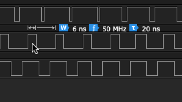
Logic analyzer capture, showing the rails constantly oscillating at a high rate

When Your Level Shifter Is Too Smart To Function

By now, 3.3V has become a comfortable and common logic level for basically anything you might be hacking. However, sometimes, you still need to interface your GPIOs with devices that are 5 V, 1.8 V, or something even less common like 2.5 V. At this point, you might stumble upon autosensing level shifters, like the TXB010x series Texas Instruments produces, and decide that they’re perfect — no need to worry about pin direction or bother with pullups. Just wire up your GPIOs and the two voltage rails you’re good to go. [Joshua0] warns us, however, that not everything is hunky dory in the automagic shifting world.

During board bring-up and multimeter probing, he found that the 1.8 V-shifted RESET signal went down to 1.0V — and its 3.3 V counterpart stayed at 2.6V. Was it a current fight between GPIOs? A faulty connection? Voltage rail instability? It got more confusing as the debugging session uncovered the shifting operating normally as soon as the test points involved were probed with the multimeter in a certain order. After re-reading the datasheet and spotting a note about reflection sensitivity, [Joshua0] realized he should try and probe the signals with a high-speed logic analyzer instead.

Continue reading “When Your Level Shifter Is Too Smart To Function”

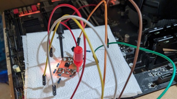
Probes connected from a Pi Pico board to the SPI flash chip, with other end of the probes connected tot the level shifter circuit resistors

Motherboard Revived With Simplest 1.8V SPI Shifter Ever

If you have ever had to fix a modern desktop motherboard, you might have noticed that the BIOS (UEFI) SPI flash is 1.8V – which means you can no longer use a Raspberry Pi or a CH341 adapter directly, and you’d need to use a 1.8V level shifter of some sort. Now, some of us can wait for a 1.8V level shifter adapter from an online store of your choosing, but [treble] got a “BIOS flash failed” motherboard from Facebook Marketplace, and decided to make it work immediately.

She tells us a story about reviving the motherboard, and there’s one thing she shows that is interesting in particular – a very simple way to level shift 3.3V signals from a serprog-flashed Pi Pico down to the 1.8V that the flash chip required, something you are guaranteed to be able to build out of the parts in your parts bin, only requiring nine resistors and an NPN transistor. If you ever need to reflash BIOS on a modern motherboard, take note. As for 1.8V rail, she ended up tapping the 1.8V power pin of the SPI chip the motherboard itself to power the chip while programming it.

In the end, after swapping the two BIOS chips places and fixing a broken trace mishap, the motherboard booted, and works wonderfully to this day, a much-needed upgrade to [treble]’s toolkit that allows her to do RISC-V cross-compiling with ease nowadays. This is not the first time we see people reflash modern boards with 1.8V chips – if you want to learn more, check out this incredibly detailed writeup! Need to do some further debugging? Use your Pico as a POST card!